Bose A20 Auto On Modification
By Matt Dralle - Version 1.0 - July 9 2011
Update - Version 1.1 - December 31 2011
dralle@matronics.com
Using Aircrft Power - Need For A Bose NR Power Switch
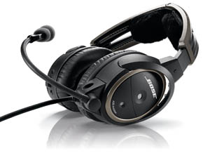
The Bose A20 noise canceling headsets are fantastic. The Noise Reduction (NR) is excellent and the audio quality for listening to music mixed with the ATC is outstanding. If you own your own aircraft, you can get a panel mount jack for the headsets that will also power the NR circuit from the aircraft power and eliminate the need for an endless supply of AA batteries. With the previous model of the Bose headsets, the "X", when you plugged them into the panel mount jack, you could put the NR slide power switch in the ON position and never have to think about whether they were on again. They simply came on with the aircraft's master switch. Very nice design.
Along comes the new A20 model and lo and behold, the slide switch for the NR power is now replaced with an electronic Push On/Push-and-hold Off switch arrangement. So now, even if you have your new Bose A20's powered though your aircraft power system, you still have to press the NR On button EVERY TIME you start the aircraft! Are you kidding me!?
The Modification
I couldn't sit still for that engineering oversight on Bose's part, so I spent a some time taking the Control Module apart on the Bose A20 headsets and came up with a fairly simple solution to the problem. The fix requires that the Control Module be completely disassembled and a surface mount 1.1 uF capacitor be soldered across the leads of the headset's power switch. How it works is that when the headset is off, the capacitor is not charged and looks like a "short" or in effect like the button is being pressed. When power is applied to the headset, for a moment, the capacitor is shorting the power button and appears that user is pressing the button which turns the NR circuit on. Once the capacitor charges up, it looks like a big resistor and is no longer shorting the power button. It works amazingly well, and I never have to worry about turning the NR on again. Why didn't Bose think of this?
For Panel Powered Installation, But Compatible with Battery Use Too
The modification is generally only for installations that are panel-powered, but you can do the modification to a unit that is normally battery powered with no adverse effect. With the modification, the NR Power button will work normally in battery power installations.
NR Power Button Still Works
After the modification and even in panel power installations, the NR Power button can still be used to power the NR off and then on again.
Photo Documented Modification Process
I photo documented the modification process below, and added step-by-step instruction text to each photo. You'll need some pretty small tools and in particular a VERY small soldering iron to pull it off. Don't try to use a normal sized soldering iron to do the modification. You will damage the PC board and push button. You need a soldering iron made for doing surface mount sized work and that has needle-like tip on it.
It goes without saying that this little modification will probably void your warrantee. You've been warned.
IMPORTANT NOTE REGARDING THE PUSH BUTTON AND SOLDERING
The push button has a small metal shell over the top with arms that go down over the side and hook over small black nubs. These are NOT the leads of the switch!!! The lead pads are UNDERNEATH the switch and you have to make VERY sure that you don't get a solder bridge between the pad and that metal top shell! Get a good magnifying glass to do the soldering work.
Contracting The Project Out
If you really want this modification, but your patience or tool set isn't up to the task, I can do the modification for you. The charge will be $100 plus return shipping. I can accept credit card or PayPal payment. Turn around will generally be a couple of weeks depending on what's going on. Email me directly at dralle@matronics.com for more information.
Bose A20 Auto Power On Modification Procedure Remove Battery Cover Screws
.jpg)
Cable Grommet Retainder Spring Clip
.jpg)
Spring Clip Removal Process
.jpg)
Clip Removed Correctly
.jpg)
Removal of Battery Holder - Note Plastic Standoffs
.jpg)
Removal of Top PC Board
.jpg)
Remove Two Screws From Bottom PC Board
.jpg)
Pull Bottom PC Board Out of Control
.jpg)
Turn Bottom PC Board Over to See Push Button Power Switch
.jpg)
Note the Pin Out of the Push Button
.jpg)
Add 1.1uF Surface Mount Capacitor with Wirewrap Wire
.jpg)
Do Not Get Solder Between Lead And Metal Switch Top!
Glue Capacitor To PC Board with Krazy Glue
.jpg) Revision History
Revision History
Initial - Version 1.0 - July 9 2011 Update - Version 1.1 - December 31 2011 - Changed capacitor value from ".1uf" to "1.1uf" for better auto-on reliability on certain A20 headphones.