|
|
Bob's Shop Notes: |
|
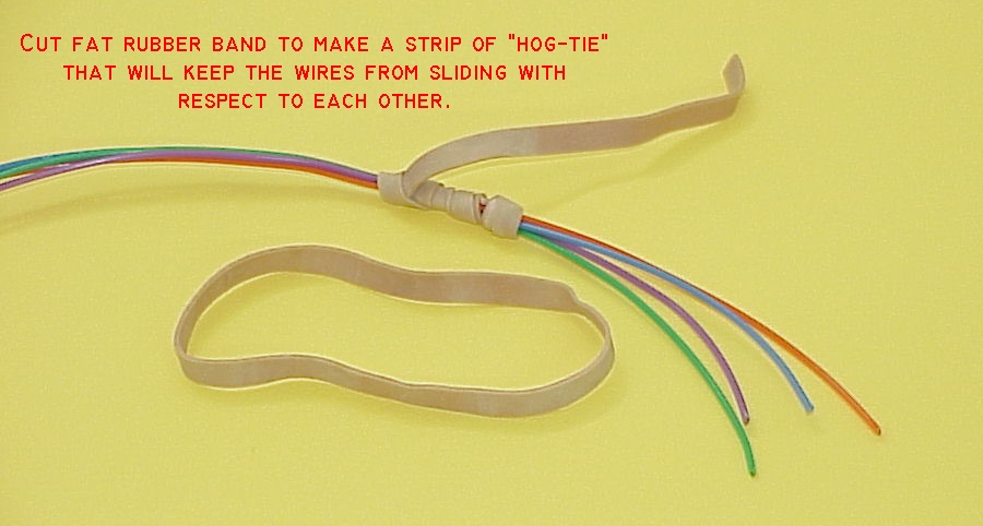
Step 1 . . .Tools needed: (1) Wire cutters, (2) wire strippers, and (3) crimp tool for PIDG-style terminals and splices. Materials needed: (1) Fat rubber bands (2) modern wire suited for use on airplanes. Mil-W-22759/16 is used in this example. Raychem Spec55 wire is also quite suited to this task, and (3) terminals and splices with metalic liners in the insulation grip . . . . Getting Started: Cut rubber band and use strip of rubber to bundle the loose ends of the wires to be joined into a single crimp. The task here is to immobilize the wires with respect to each other so that one or more strands don's shift out of alignment during the insertion phase. Multiple turns of rubber band in tension will supply sufficient friction and force between the strands to accomplish this task.
|
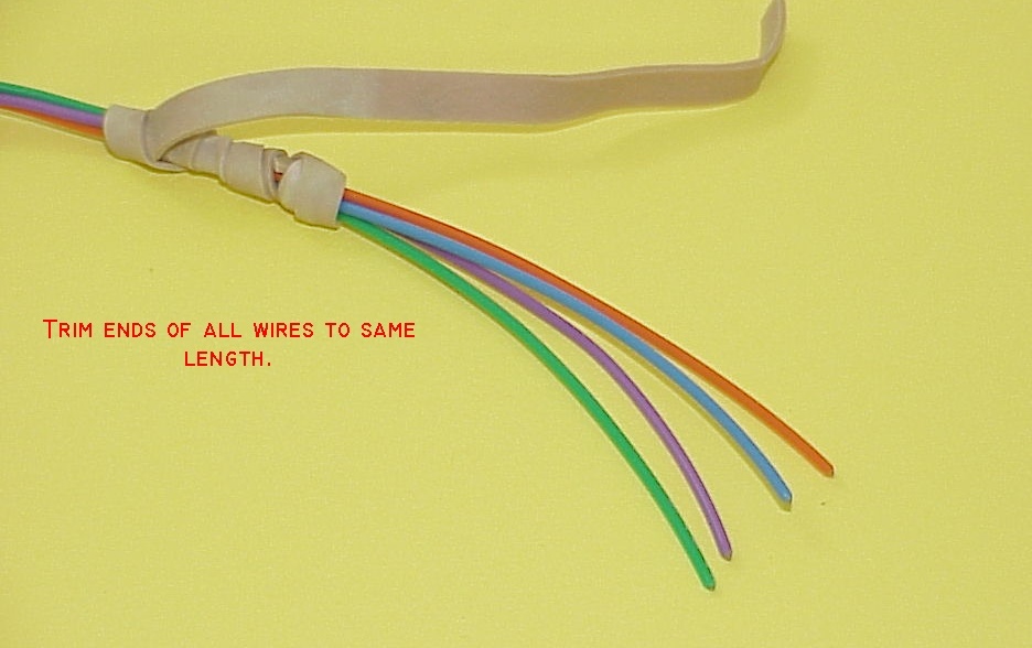
Step 2 . . .Here I'll demonstrate the termination of four 22AWG conductors by a single red (18-22AWG) PIDG terminal. This particular wire is Mil-W-22759/16. Cut all strands to same length . . . |
|
|
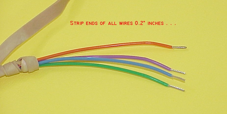
Step 3 . . .Strip ends expose 0.2" of wire on each conductor . . . |
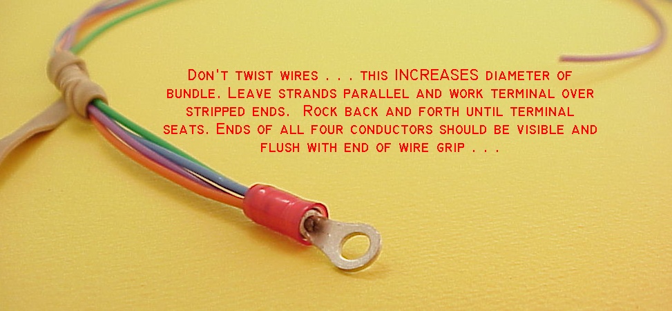
Step 4 . . .You may be tempted to twist the wires but resist the urge. This will make the bundle of wires LARGER in diameter making it difficult to insert the wires into the terminal. It will also ENCOURAGE strands to leave the fold as it were and become bunched up down around the insulation. Use a gentle rocking motion to tease the strands into the terminal or splice's wire grip. It won't take any force to get the wires properly seated. If it does require much force . . . you're probably trying to put too much wire into the terminal. When you're ready to crimp, all strands should be visible at the open end of the wire grip. With PIDG-Style nylon splices, you can see the strands through the relatively transparent outer jacket. Note that when the wire are seated, all the strands lay nicely parallel to each other between the terminal and the hog-tie showing that no bunching has occurred inside the terminal. |
|
|
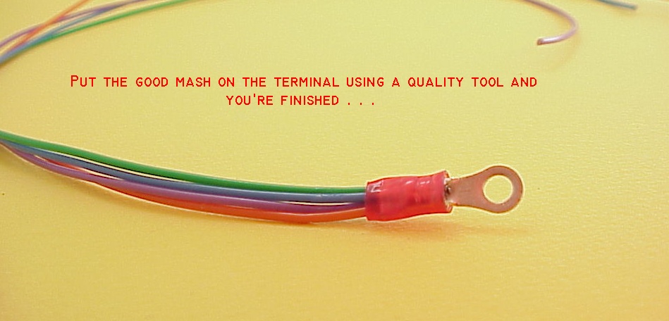
Step 5 . . .Put the mash on it with your crimp tool, remove the hog-tie and you're finished.
|
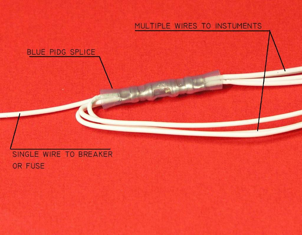
Practical Example . . .
Hi Bob, Total current draw for your instruments won't exceed 5A so a single 5A fuse or breaker will be suited to protecting 22AWG power wires. Using techniques described above, use a splice to fan out a single supply wire to multiple instruments as shown here. |
|
 Click here to contact Bob at AeroElectric Connection Click here to contact Bob at AeroElectric Connection |