 |
Matronics Email Lists
Web Forum Interface to the Matronics Email Lists
|
| View previous topic :: View next topic |
| Author |
Message |
nuckolls.bob(at)aeroelect
Guest
|
 Posted: Thu Apr 14, 2016 12:39 pm Post subject: RF Interference Posted: Thu Apr 14, 2016 12:39 pm Post subject: RF Interference |
 |
|
At 12:34 PM 4/14/2016, you wrote:
| Quote: | I've got a question about substituting a battery for the sender's output.
In my (somewhat dim past) experience, the impedance of the line in question had a major effect on its vulnerability to noise induced on it. So.... is this a valid test? I'd assume that the internal impedance of even a AA battery would be much lower than any electronic sensor normally used around an engine. |
The purpose of this test was to divide an conquer.
Until the sensor (a variable voltage source with
ACTIVE hence vulnerable components) then we
are unsure whether the vulnerability is in the
signal source or the panel display.
It isn't the WIRE with a vulnerability, it is
merely a conductor (first) and perhaps an antenna
(second) which carries the antagonistic energy
into the victim. Adding inductance reduces the
wire's ability to conduct . . . as demonstrated
in the video.
99% of the time, the victim is some solid state
device that is being forced out of it's normal
operating boundaries by the interfering energy.
This experiment gave us a high order of confidence
that the transducer is the victim.
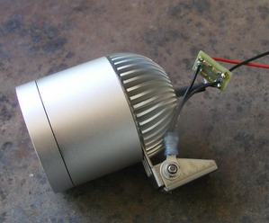
The itty-bitty filter is about 0.4 x 0.8 inches.
It was crafted and first used on an LED lamp
assembly being considered for an ultralight.
It did limit VHF emissions sufficiently to
make this fixture useable.
[img]cid:.0[/img]
I've since shipped out several to other builders
but I don't think I've heard back.
The ferrite chip inductors were rated for
700 ohms reactance at 100 mHz, the monolythic
chip capacitors on either side are on the order
of 0.1 ohms . . . so I would expect this
assembly to be an excellent fire wall at
VHF comm frequencies for CONDUCTED noise,
probably so good that any problem energies
remaining are likely to be RADIATED for
which solutions are different.
I've got a new spectrum analyzer and tracking
generator that's still in the box. As soon
as I get some time to have some 'fun', I'll
be able to quantify the effectiveness of
such devices over a range of frequencies.
I sure do miss access to the EMC labs at
Hawker/Beech!
Bob . . .
| | - The Matronics AeroElectric-List Email Forum - | | | Use the List Feature Navigator to browse the many List utilities available such as the Email Subscriptions page, Archive Search & Download, 7-Day Browse, Chat, FAQ, Photoshare, and much more:
http://www.matronics.com/Navigator?AeroElectric-List |
|
| Description: |
|
| Filesize: |
45.54 KB |
| Viewed: |
1432 Time(s) |
|
|
|
| Back to top |
|
 |
nuckolls.bob(at)aeroelect
Guest
|
| Posted: Thu Apr 14, 2016 12:57 pm Post subject: RF Interference |
|
|
| Quote: | Your itty-bitty filter:
1. how big is it? perhaps put a penny in the picture |
about .4 x .8 inches
| Quote: | | 2. when you designed the filter, what frequency are you trying to filter? I'm guessing it's somewhere in 110-140 MHz but what about harmonics? |
yes, the parts are 'speced' in the VHF comm
range but effectiveness of the array extends
upward a decade or more.
| Quote: | 3. are those tiny surface-mount components an inductor & a cap? (or is it the case that: "you could tell me but then you'd have to kill me?"  |
No big deal. Pick a series reactance from
this array of possibilities . . .
http://tinyurl.com/zn4knzj
Primary concerns are current trough the inductor
and voltage drop in the inductor. Then see
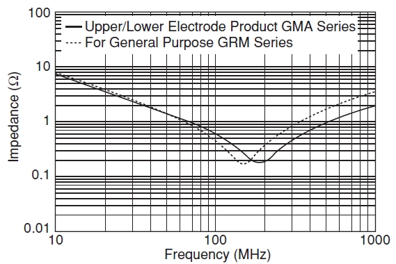
| Quote: | how high a reactance you can get within space
and volume concerns. Capacitors either side need
not me more than 1 to 10 nF . . . These monolythic
capacitors have 'dips'in impedance in the
regions around VHF comm . . . but still quite
useful over the regions on either side.
[img]cid:.0[/img]
Designing these filters is not very technical.
They're easy to craft with a brute force approach
to energy attenuation above 20 MHz or so.
|
Bob . . .
| | - The Matronics AeroElectric-List Email Forum - | | | Use the List Feature Navigator to browse the many List utilities available such as the Email Subscriptions page, Archive Search & Download, 7-Day Browse, Chat, FAQ, Photoshare, and much more:
http://www.matronics.com/Navigator?AeroElectric-List |
|
| Description: |
|
| Filesize: |
129.23 KB |
| Viewed: |
1431 Time(s) |
|
|
|
| Back to top |
|
|
|
|
You cannot post new topics in this forum
You cannot reply to topics in this forum
You cannot edit your posts in this forum
You cannot delete your posts in this forum
You cannot vote in polls in this forum
You cannot attach files in this forum
You can download files in this forum
|
Powered by phpBB © 2001, 2005 phpBB Group
|

