The stiffeners come already cut to shape, and both skin and stiffeners are pre-drilled! :-) Stiffeners are drilled to the skin as for the rudder, etc. and the skin and stiffeners dimpled; straightforward stuff. Mark the stiffeners carefully; they all look the same, and there's a lot of them. Back-rivet them together and squeeze the TE as for the elevators, including the drinking straws and RTV.
Since the 2 ailerons are mirror-images of each other, you need to be careful of which parts will belong to which aileron. To minimise these problems, I'm building the left aileron first, and work on right aileron parts only when the corresponding left part has been riveted to something else. Or else mark each part very clearly.
The spars can be lightened by drilling a series of 2" circles in it. I used a hole-saw for these; although the saw was intended for wood it worked well, so long as minimal downward pressure was put on the drill. Be careful: too much pressure results in jagged, out-of-round holes. Note that the aileron spar is not a simple channel; the top flange is bent at a different angle to the bottom flange. Be sure to clearly mark the top and decide which is the left and right spar before drilling the lightening holes. (Actually, that's not all that critical -- the space at the tip end is only 1/8" less than at the root end).
The aileron counterbalances are pieces of galvanised water pipe (do they really need to ship this stuff with the kit?); you'll need to cut in half the piece of pipe that's in your kit. WC says to make this 45 3/8" whereas Van's says 45 15/16"; I went with Van's.
Be careful when reading plan 16. The diagram in the top left corner shows a Left aileron, whilst that in the top right shows a Right aileron spar.
BEWARE: When assembling the aileron skeleton, the manual implies that the A408 spar reinforcements and the A404 nose ribs go on before the A405 ribs. FJ's notes also suggest this, as do WC's. I guess that Van's has changed things with the pre-punched kit. If you're going to follow the manual, you must put the A405 ribs on first, since the AN426AD3-4 flush rivets go underneath the A408 reinforcement plates. If, like my first attempt, you didn't do this, you can follow FJ's notes and countersink the A408 for these rivets... you'll need some longer rivets too. The ribs will also be attached by the bolts which hold the aileron brackets on, so I guess these rivets aren't important structurally anyway.
Use your flange centreline marking tool to mark a line 5/16" in from each end of the spar, clamp the ribs in place, then drill the 2 #40 holes through the spar into the rib. FJ's notes, and the diagram bottom left of plan 16 give 1" as the distance between these rivets. I reduced that to about 1", since otherwise these rivets will be very close to the bolts. In fact, it might be a good idea to reduce it to 3/4".
When dimpling the main rib attach holes in the spar, ensure that the spar web doesn't bend. Mine did, and I believe that was the cause of a twist in the aileron which eventually resulted in a complete rebuild.
I couldn't think of a neat way of cutting out the "mouse-holes" in the root ribs. I drilled a series of #40 holes inside the mouse-hole outline, then filed it smooth. Or at least smoothish; I couldn't get a really nice semicircle.
It took a little figuring to sort out the drilling of the nose ribs, spar, and
A408s so that they all matched, but not too impossible. I differed a little
from WC's notes here. The problem is in lining up the nose ribs when you attach
them to the reinforcing plates and spar. My solution was to first drilled #40
the 6 rivet holes in the A408s (measure and mark one each of the root and tip
A408s, then drill through both of each kind). These were then drilled to the
spar. I could then align the centre of the nose rib flange with the 3 holes in
the A408 and drill through. Finally, I drilled #30 through the
spar/A408/nose-rib. ![]()
Be careful to ensure the skeleton is very straight when drilling and riveting on the counterbalance. Maybe clamp some angle to the spar to ensure it stays straight. I found I had a bad twist (half inch or so) in the aileron skeleton when it was finally riveted. The clecos stopped me noticing it earlier. I drilled out one pop-rivet from the counterbalance and shimmed it, but this didn't totally eliminate the twist. I thought that, when I drill out the temporary rivets, I could shim one of the tip ribs to line everything up. In the end, that wasn't possible; once riveted together, the aileron is very rigid and impossible to twist straight. Bill Benedict at Vans said "It will be airworthy, but I would drill the CS4-4 rivets out of the bottom, flatten the aileron out, drill three new holes, one on each end (between existing holes) and one in the middle to hold everything in place, then run a drill through the existing holes and re-rivet it back together. Should work fine. If you need to, add more rivets between the existing rivets, depending on how much you need to open up the existing holes." I tried this; however, this didn't straighten it out properly, I think because the twist was in the skeleton. I've now decided to build another left aileron.
On my second attempt, I pop-riveted the bottom rivets into the counterbalance first. With clecos in the top holes, it looked like the skeleton was going to be twisted again. However, I shimmed these holes and everything came out straight. I think this technique is a MUST.
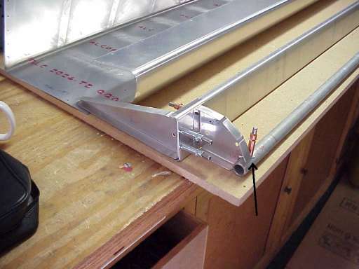
Adrian Chick <adrianchick@home.com> wrote: Regarding your problem with the aileron, I can't help much because I haven't started my wings yet. But, you might be experiencing the same thing that a friend of mine experienced. He noted that the weight of the tube would help hold the spar down, but even then there was a slight gap. I'm sending you a photo of his aileron, and the arrow shows where he was intending on putting a shim. I think Van's told him not to worry about it, and I personally think he should have let it go. The part where the tube is won't even be in the flow of the airstream as I understand it. So, for what it's worth, here it is...
RV-List message posted by: kennett@direct.ca (robert kennett): The following worked for me on my RV-6 ailerons. All drilling was completed on a flat surface with the assembly weighted down.
2) Drill top of spar to skin
3) Drill top of end ribs
4) Flip aileron over with top spar clecos hanging over edge of flat surface
5) Drill bottom of spar to skin
6) Drill bottom of end ribs
7) Drill skin to counterweight.
For riveting:
1) Top spar to skin first in a V-jig.
2) All subsequent riveting done on flat surface with aileron weighted down.
3) Top of end ribs
4) Inspection as required (in Canada).
5) Bottom spar to skin.
6) Bottom of end ribs
7) Counterweight to skin.
A similar procedure was used for the flaps (i.e. as much drilling and riveting as possible with the flap on the flat surface)
When drilling the skin to the skeleton, first mark centrelines on all the spars and ribs. You can then align these through the holes in the skin. Actually, I suspect the best approach would be to line things up with the skin when building the skeleton.
I drilled the top skin first, on a flat surface. Spar first, centre outwards.
Again, maybe clamp some angle to the spar to ensure it stays straight. Then the
drill main ribs to the TE, then the nose ribs. ![]() To
drill the bottom skins, I used a jig rather than the technique recommended by
Van's. This is the same jig as used for the flaps. First drill the skin to the
counterbalance, then to the nose ribs, main ribs, and finally the bottom spar.
Not sure whether this is the best order, actually.
To
drill the bottom skins, I used a jig rather than the technique recommended by
Van's. This is the same jig as used for the flaps. First drill the skin to the
counterbalance, then to the nose ribs, main ribs, and finally the bottom spar.
Not sure whether this is the best order, actually.
One of the major reasons NOT to put RTV in the ailerons is that you will no longer be able to squeeze/un-squeeze the trailing edge radius to effect trimming out for a heavy wing condition. This is a common thing to do and is very effective. This has been discussed and recommended by Van's. Also, If you end up with a bulbous trailing edge on your aileron with RTV in it, you are in for some trouble. A result of this is commonly described as "aileron snatch" and has gotten the attention of more than one experienced RV pilot.
On my second R aileron, I found things badly screwed after I'd drilled all the holes through the skins into the bottom of the spar. It seems I'd pulled the skin down too tight, so that it bowed in the middle. Consequently, the holes I drilled through the pre-punched skin holes hit the edge of the spar flange in the middle, and were a few mm out nearer the tips. After thinking about it for a *long* time, I eventually drilled another row of rivets just forward of the original row, and midway between them. I measured how far the original row of holes was from the spar flange centreline, then marked my new holes that far forward of the original holes in the skin. This row went right down the centre of the spar :-) After riveting together, this aileron is nice and straight. I dimpled the original holes and will use 3/32" aluminium pop rivets to fill the holes.
Riveting the top of the skin to the skeleton spar will make you sympathise with the person who helped buck your HS skins; an awkward job with the stiffeners of the bottom skin pressing/cutting into the back of the hand holding the bucking bar. The rivets (there's several) which line up with the ends of stiffeners are especially awkward.
"When riveting top skin to aileron spar, I used the same bucking bar Orndorff used in video. Put 4 nasty marks on skin before I got smart and made up a little guy to use in there. It's amazing how little mass is needed to buck 3/32 rivets."
Someone (can't remember who) sent me this drawing of his aileron bucking bar.
"Be sure to remember the old mirror-image number when making aileron brackets. I *almost* screwed up here on that one with the three holes."
Jerry Walker <Carrabell@aol.com> wrote to the RV-list: "We took a 4' X 6' piece of particle board that we often use for a work bench top and fastened it with a 6 to 8 inch overlap vertically on one of the 4 X 4 of our wing jig. We left a 4" gap at the bottom. Take your aileron and clamp the leading edge so that the bottom of the spar is on the surface of the particle board and the bottom skin will clear the particle board so that you can open it up to get inside. This will make the aileron very rigid and you can easily (tongue in cheek) get to the rear of the spar with your bucking bar. The most dangerous areas are where the rivet are near the stiffeners. Our solution was to machine a piece of steel about 1" x 1.5" x 1/2" at an angle comparable to the angle on the spar and use it to buck the rivets." This sounds like a great arrangement to me.
RV-List message posted by: Larry Olson <lolson@doitnow.com> Regarding riveting the aileron top skin to the aileron front spar: I used my trusty Avery #615 bucking bar. But be careful not to let it hit the skin about mid way between the spar and the trailing edge. It will dent it from the inside. Duct tape on the bucking bar would probably help. Also I taped a 1/4" x 7/16" x 2" piece of balsa to the bottom so it could ride on the spar and be the correct height to match the rivet line.
RV-List message posted by: Gordon Comfort <gcomfo@tc3net.com> regarding
riveting the Ailerons together:
I made a bucking bar system that can be used on the ailerons, either top or
bottom, or both. It consists of a bar of cold rolled steel 3/8" X
1-1/2" and about 60" long. The exact size is not crucial. To this I
affixed with double faced tape a small bar that began life as 1/2" square
and 3" or so long. This bar was ground to a bevel approximating the
included angle of the spar flange. The aileron was fixtured so that the
riveting could be done from below with the bar resting in the spar channel. The
bar was taped to minimise scuffing. With a bit of practice it was easy to
insert the rivet with a thumb, slip the mushroom rivet set onto it, seat the
rivet by pushing hard enough to lift the bar assembly and shoot the rivet. It
is necessary to leave the end ribs out while this is done. A helper to position
the bar speeds things up considerably. The crick in your neck goes away pretty
soon. This enables closing the aileron with driven rivets.
I found it hard to tell from the plans whether the front or back of the skin overlaps on the outside; I decided after minute examination of the plans that it was probably front over back, rather than vice versa. It also ought to be more streamlined, I guess.
RV-List message posted by: Doug Gray <doug.gray@hlos.com.au> For the aileron assembly I needed to come up with a sequence to ensure I would hit the spar through an underlying skin. I used the following sequence:
1. Fit the skeleton inside the PP skin.
2. Align the PP holes with a previously marked Centre Line marked on the top
spar flange. Drill and cleco the skin to spar.
3. Turn the Aileron over, clecos hanging over the edge of a flat table surface.
4. Lift and prop the TE skin up and away from the spar if TE bend already
completed. I found it better to leave the TE unbent (as shipped) for this step.
5. Using edge-grip clamps clamp the skin LE to the bottom spar centring the pp
holes with the previously marked centreline on the spar flange.
6. Drill and cleco the LE skin to the spar through only enough pp holes (I
drilled only 5 at equal spaces along the spar) to be sure the spar will be held
in place with the clecos. The remainder will be drilled later.
6. Mark the LE skin with a felt pen to indicate the position of these drilled
holes.
7. If not already done complete TE bend.
8. Remove clecos and slip the TE skin under the pp LE skin.
9. Weight the skins with large (telephone) books on a flat surface.
10. At the centremost location where the holes were drilled through (marked on
the skin), very carefully drill partially through the .016 skin underlying.
Remember it is unlikely that the spar will be correctly located so don't drill
through the skin.
11. Remove the books and lift the TE skin away from the spar, then drill through
this partially drilled hole in the skin.
12. Cleco the skin LE, TE and spar together through this hole.
13. Repeat 9 thru 12 for each of the 5 predrilled locations. Cleco through all
drilled holes prior to drilling the next.
14. Drill the remainder of the skin/spar holes through the pp holes.
The skin is now drilled to the spar smack down the centre of the spar flanges.
I riveted using the US Industrial bar #638 (Avery does have a similar bar) after the side was polished. It fits nicely into the spar channel with the cutout clearing the skin stiffener angles. Duct tape on the bar protects the spar. This was awkward but not at all difficult.
Heavily mark and index everything. Left, right, tip, root, up, down, front, rear... on both sides. There's a lot of potential here for mix-ups.
Not mentioned in the plans, but FJ says to cut the hinges to 55 1/2" (my hinges as received were 60" long).
Mark centrelines on all the rib and spar flanges. Taper the root end of each spar as shown on Plan 17.
I drilled the bottom skins to my spars first (3/32") ![]() ,
then drilled the spars to the hinges (3/32"), then finish-drilled skins,
spars and hinges #41.
,
then drilled the spars to the hinges (3/32"), then finish-drilled skins,
spars and hinges #41.
I believe drilling spars to skins first was a really good idea; the short FL-404 ribs are about 1/8" too short. If I'd used the ribs as described in the manual to set the spar's position, I'm sure the holes through the spar and hinge would not have maintained edge distance properly. I thought I might have to shim the TE of the short ribs; instead I bent the bottom skin flange a little to meet the TE flanges of those ribs. Alternatively, you could unbend and then re-bend the rear flanges of the small ribs to assure a tight fit.
The angles of the flanges on my spars were a long way out; I had to bend them to meet up with the front flange of the ribs. Best to do this before drilling the lightening holes in the spar (in fact, I left drilling the lightening holes until last because I figure it leaves the spar a little stiffer whilst working with it). Of course, the ribs' flanges also needed squaring up.
Drilling ribs to spar and bottom skin: mark and drill #41 the rivet holes on the
front flanges of the ribs. Mark and drill #41 the rivet hole in the rear flange
of the short ribs -- nearer the bottom than the middle. With the spar clecoed
to the bottom skin, clamp each rib to the spar and skin (line up centreline
with holes) and drill through the skin into the rib. ![]()
NOTE: Do NOT drill the root rib to the spar yet. In fact, don't do anything with the root rib except drill the bottom skin to it #41.
Now back-drill #30 through the short & tip ribs into the spar. Finally, back-drill #30 through the rear flanges of the short ribs (I used an aircraft drill through the bottom hole in the front spar and flange).
Make the FL-606 unit. It's not simple; because the root end of the spar is tapered, the root rib's web is not vertical. And the FL-606B is also not mounted vertically. And neither the rib nor the FL-606B is at right angles to the spar either.
Cut the FL-606A from the angle. Note that the surface which mounts to the front of the spar is not rectangular, due to the taper at the root of the spar. Drill the holes in it #30, drill it to the spar, and the root rib. If making both FL-606As at once, note that they are different.
Cut the FL-606B from the plate (I actually did this way back when I cut the rear spar items out).
Cut the FL-606C from the 3/4" .063 angle, and taper as instructed. If making both FL-606Cs at once, note that they are mirror images (I have a spare Left FL-606C now!) Drill #30 through the skin and root rib into the FL-606C. Countersink these holes in the FL-606C, dimple them in the skin and root rib. Clamp the FL-606B & C together and drill together #30 (except the last hole -- drilled 1/4" in assembly!). Cleco together, cleco FL-606C to skin & root rib, FL606A to spar.
Now bend the FL-606B as shown in the plans. This is easier said than done! I locked my FL-606B in the vice, then C-clamped 2 2ft angle irons either side of it. These gave me enough leverage to bend the plate.
Finally, drill 5 holes FL-606B to FL606A #30. ![]()
I think it's worth building a simple jig (like the rudder and elevator jigs from the empennage). Mark the tooling line and outlines of the long ribs on some particle board and cut them out. You'll need a couple of parallel edges so that when you plumb them up, the V's in the jig are lined up properly. Make the 2 pieces opposite orientation, (like bookends) to facilitate this.
"I cut my jig pieces out of 3/4 fibreboard...clamped 'em together with rib
outline on top and cut like a triple-decker sandwich with Skilsaw.
I had indexed them on edges and had line drawn thru tooling holes. The whole
project including screwing them to bench didn't take an hour. I think using
tank cradle to rivet flaps would be asking for trouble. As it was, I got two
"smiles" on the bottom skin (whew!) as a result of the assembly
jumping around in the jig. Then I got smart and tightened up the cutouts from
the jig with duct tape so they wouldn't rattle loose."
Place the bottom skin/spar/ribs in the top skin in jig. Line up holes in top
skin with spar flange centreline and rib centrelines. Check flap chord
measurement (10 1/2" from spar to TE) (or maybe don't check it... what are
you going to do if it isn't right?). Drill top surface of top skin to spar,
then to ribs. Drill the bottom of the top skin to the bottom skin, starting
from the middle and working outwards. Then drill the bottom of the top skin to
the long ribs. ![]()
Countersink the holes in the bottom spar flange and dimple the skins and ribs. Note that there's one hole on the spar at the root end which doesn't need to be countersunk (or did I cut my hinges too short?)
The bottom of the top skin overlaps the bottom skin. I tapered down the edge of the top skin back to about the edge of the dimples to streamline the join a little. I think this edge also needs to be folded a little, as for the ailerons and other overlapping skins so that the edge won't bend up when the skins are riveted together.
There are 13 lightening holes in the spar (4 groups of 3, and one single one), and 17 in the brace. These numbers aren't evident from the plans, but do show up on the video.
Now, deburr and dimple all those holes, prime, reassemble, jig, and rivet. Note pop rivets in the root rib. (There ought to be more notes on riveting, but I forgot).
The top flap skin will be trimmed back to align with the edge of the FL606 which will eventually attach to the flap control link rod. This would have been easier to do before the flaps were assembled. The hole for the flap control link rod, marked as "drill in assembly" in the plans, can be drilled to 1/4" immediately. There is no practical way to drill this hole in assembly!
Tom Martin <fairlea@execulink.com> wrote to the RV-list: Leave this part unfinished until you mount the wings to the fuse. Sometimes the flap is too close to the body of the aircraft and the flap can then be adjusted to fit. The whole thing will make sense when you see where it is supposed to go.
Trimming the inboard end of the flap: I've just finished my RV-6 flaps and the fit up to the fuselage with very good results and thought I'd pass on what I learned.
First, during the wing construction I riveted up the bottom skin of the flap with its ribs except for the inboard one which I only drilled. The spar was drilled to the ribs and the bottom skin with the hinge but only clecoed on. Make sure that the spar is tight against the ribs when you drill it the the bottom skin or later you could induce a twist into the assembly.
Using I think Frank Justices method of installing and aligning the ailerons and flap I positioned the wings vertically with the nose down. The wing top skins were riveted on but the bottoms were still only clecoed. Following his procedure I aligned and installed the aileron hinges and flap hinges with the aileron and bottom flap assembly in place (his procedure uses the tooling holes for alignment and no wing profile). The top flap skin trailing end was aligned with the aileron trailing edge and a couple of alignment holes were drilled to locate it to the bottom flap assembly. The inboard linkage attachment pieces were not yet installed. At this point I set the uncompleted flaps aside and proceeded to finish the wings and build the fuselage.
(Fast forward 2 years)
After getting the fuselage on the gear and the wings installed I was now ready to complete the flaps. I drilled the top skin to the bottom assembly. With the top skin off I put the bottom flap assembly onto the wing. This allowed me to mark edge of the fuselage onto the bottom skin. THIS IS NOT FOR CUTTING, It is for locating the inboard flap linkage plate.
Next, I used poster board to make a template that when set on top of the inboard two flap ribs would reach from the spar to the trailing edge of the inboard rib and would follow the fuselage contour. This is easy to do with scissors using trial and error. This was taped into place as if it were the top skin. Take the flap off of the wing and set it on a bench, position the top skin and cleco into place with the template still in place. A few clecos can actually be pushed through the template. Flip it over and trace the edge of the template onto the bottom side of the top skin. Remove the top skin, extend the trim line to the front and rear. Cut along the line. At approximately 1/2" from the trailing edge, angle the cut off to the inboard edge. This area will be final trimmed on the fuselage. After filing the edge, cleco the top flap skin on and reinstall onto the wing. Pivot it up and trim the last 1/2" with a rat tail and small straight file. You should now have a perfect fitting top flap skin to fuselage intersection. Please remember that the bottom skin DOES NOT GET TRIMMED.
With the flaps off the wing and the top skin off the inboard brackets can be made. The fuselage line on the bottom skin will be used to position the inboard linkage attachment plate. This plate should be at 1/8" away from the fuselage.
*******************************
I worried a lot about twisting as it was mentioned in archive search. Here's what I did: after ribs were riveted to the bottom skin and top skin was slipped into position, I clamped it firmly to the workbench with some scrap .125 via clecos drilled into bench. One each at each corner of the trailing edge of top (wraparound) skin. This pretty much guaranteed that the top skin rivets in ribs would be perpendicular to bottom skin.
I split my piano hinges as per the RVator. Added one rivet where cut line was right on existing hole.
For what it's worth, I talked to Vans about the hinges and as usual, they were equivocal. When pressed, the guy I talked to (I don't try to keep track of which one I get when I call) allowed that he had the single hinge on his 4 and was difficult to install. I pointed out that the RVator article said 2" in text, 3" in sketch. He said either was fine. When I first clecoed the hinges in place on flaps, one was smooth as could be, the other needed a spin with the hand drill and a shot of lubricant to be movable at all. I started thinking, "What were the odds of getting everything real straight when it was hung on the wing?" Net was I figured split was the logical choice for a doofus like me. All four of the shorter hinges are quite smooth.
I believe I can still cut a loop or so out of my hinges so that I can put the pins in from the middle. Time will tell...
Whilst drilling the hinge to the flap, drill identically placed holes in the other half of the hinge. FJ tells you to do this later, after the first half has already been riveted to the flap. Much easier to do it now.
There are pictures of wing stands available on the Net, but no dimensions given. The cradle is just a frame, with strips of carpet going from one side to the other... there's no wood contacting the LE at all. When I measure mine up, I'll put the dimensions here.
I put castors under one end, and fixed wheels under the other. That was a mistake... it's awkward to move around now. Put castors at both ends.
I use a long galvanized pipe through the lightening holes. Further suggestion was to use PVC pipe or wrap the galv. iron pipe in tape to avoid unlike-metal corrosion.
Pilot drill the holes in the brackets #30. Clamp some strips of scrap to the bracket so that you can still see the chordline mark. With these resting on the end of the spar, it's easy to align the bracket nicely, then drill through the pilot holes. Finally drill all the holes out to 3/16" for the bolts. Also drill the hinge holes and the pushrod attach holes 3/16" at this point. I assembled my brackets to the aileron with hardware store bolts because I thought I might need to shim the ailerons out to align with the flaps. That was pointless... they do align, but if they didn't, I could move the flaps easily enough.
When drilling the aileron attach holes (#30 initially) on the steel brackets that fit up against the aileron spars... Might be a good idea to drill these holes about 1/8 inch more toward the centre. I ran into an edge distance problem when drilled to ailerons on two of them that will cause me to have to painstakingly enlarge toward centre to accommodate the #12 drill for the 3/16 bolts that will eventually go in there. I pilot drilled to spec but the spar-mating flange on the tip ribs was insufficient. No problem with spar.
On the side of the airfoil template, mark and drill 3/16" the location of
the aileron hinge bolt. From there, draw a line to the aileron's TE (this will
be close to the cutout). Use a protractor (or some trigonometry) to draw lines
at 32°, 30°,25°, -15°,and -17° relative to that line. These
lines will be used to check aileron movement -- no fancy digital levels needed!
Drill a hole just below the 30° line, out near the TE somewhere. That'll be
used to set the aileron stop location later. ![]()
Here's what the factory suggested to me ages ago when my poorly-cut templates gave inconsistent results: use thin strips of wood long enough to span the full chord of the wing and extend beyond the trailing and especially the leading edges. Clamp them together at the trailing edge of the aileron, one above and one below the wing. The sticks will enclose an angle equal to the cross-section of the aileron, grasping same snugly. Draw the forward ends of the sticks gently together with strapping until they follow the curves of the wing's surfaces as far as possible toward the leading edge. At some point the radius of the airfoil will become too tight for the wood to follow it; that's the stopping point. Two pairs of these sticks, at each end of the aileron, will securely locate the aileron "in trail" or "fair" to the wing as close as any method I know of. Just be sure to pad the skins against abrasion from the wood. Results are very reproducible and, hey, it's factory advice!
After attaching the lower skin, it's necessary to remove the final 1" tab of the rear spar, and the corresponding jig bracket. The wing in this state was surprisingly rigid. I followed Cretsinger mostly... other techniques can be found via the RV-list archives.
The important measurement is the one between either the centre or the bottom of the aileron spar and the pivot point on the aileron bracket. It has to be the same at both ends of the aileron. Once you have achieved this you're half way there.
I used the airfoil templates to hold the aileron in position on the wing., then
used a 3/16" hardware bolt to temporarily attach the aileron A606? (the
tip end) to the W414, and positioned that on the spar and tip rib. My
W413/W414s were pre-drilled, so WC's suggestions of using 5/8" edge
distance can't be applied. Once that was sorted out, I drilled and clecoed it
to the rib, then removed the aileron and drilled and clecoed it to the spar.
One done! ![]()
![]()
The problem with the inboard mount is that it needs to line up with the W625 half-rib. My approach was:
1. Remove the W625 half rib. Mark a centreline on its rear flange.
2. Mark a line on the rear of the rear spar web, from one of the W625-to-spar flange rivet holes to the other. This corresponds to the centreline of the W625 rib.
3. Attach the aileron mount to the aileron (in the template).
4. Align the pre-drilled holes in the mount with the marked line, and drilled.
5. Remove the mount.
6. Put W625 in place, and cleco it to the skin.
7. You should be able to see the W625 flange centreline through the holes in the rear spar. Drill through the spar into the W625.
Alternatively, you could look at the sketches in the manual (I didn't until it was too late. Doh!). Sketch 32F (I think) says to attach the W625 with 3/32" flush rivets, placed so that there's good spacing between them and the 1/8" rivets which attach the aileron mount.
BrooksRV6@webtv.net (Chris Brooks) wrote to the RV-list: "Some tips: Mount the aileron first; secure the aileron brackets to the aileron with clecos and secure both hinges to aileron brackets with bolts and spacers. Drill the outboard hinge to the rear spar with the hinge line 1 5/8" below the chord line (Drw16). Use the aileron itself to locate the position of the inboard hinge, and set it's hinge line 1 5/8" below the chord line. Put on female airfoil templates and adjust aileron brackets to aileron for final drilling for bolts. Install flap using female airfoil templates and fit to aileron.
The aileron gap seals need some trimming to make them fit. From the RV-list archives, you will need to trim almost an inch off the flat side, for the length of the seals. Apparently this extra metal was needed there for the manufacturing process. Don't trim this off until after you've fitted them... WC tells you when to do it.
RV-List message posted by: MLaboyteau@aol.com: What I did (I learned it from another builder) was to use flush rivets on the reinforcing plates and on the ribs in the areas where the aileron gap seal would set on the rear spar. Then I used the pop rivets to rivet the seal to the rear spar, but spaced in order to avoid the ribs and w-607's. I notched the gap seal slightly so it would set up on the w-607 plates. I think this is similar to how the Orndorff's did theirs, if you have access to one of their videos. On mine, I trimmed the forward pointing edge of the seal to butt up against the flange of the rear spar. I've seen some builders install this piece where it lays in between the top skin and the flange on the rear spar, in order to avoid the row of rivets that attach the seat to the top skin, but on the ones that I've seen done like this, it makes a slight joggle in the top skin at each rib. It's mostly cosmetic, so you can do it either way.
RV-List message posted by: "riveter" <riveter@ix.netcom.com>: I got word from Van's that the aileron gap seal gap needs to be 1/4 inch (1/8 absolute minimum) and uniform from side to side. This critical dimension is not in the RV4 plans nor could I find it in the manual.
I've included Doug Medema's exploded drawings of the bolts and washers in the appropriate places... here's what Doug said when he drew/typed these drawings:
From dougm@physio-control.com (Doug Medema): I have been finishing up my first wing and am not sure about the order of all the washers and spacers. I decided it would be nice to have exploded drawings of each place where a bolt is used (other than just the standard single AN960-10 washer under an AN365-1032 nut).Aileron outboard mount:I believe there are six places on each wing where this would be useful:
Bellcrank centre;
Bellcrank to aileron;
Bellcrank to stick;
Aileron inboard mount;
Aileron outboard mount;
and Aileron to bellcrank.I have attempted to do an ASCII art exploded drawing of each. I would appreciate any verifications and corrections to these.
=== AN3-10A (bolt)Aileron inboard mount:
-------- A606 (bracket on aileron)
| | Spacer
--- AN960-10 (washer)
============= W414 (aileron mounting bracket)
--- AN960-10 (washer)
-------- A606 (bracket on aileron)
--- AN960-10 (washer)
=== AN365-1032 (nut)
=== AN3-10A (bolt)For these two, make the spacers such that you have the 1/4" clearance between the wing tips and the ailerons. That may mean adjusting the spacer length or number of washers.
-------- A607 (bracket on aileron)
| | Spacer
----- AN970-3 (washer)
--- AN960-10 (washer)
============= W413 (aileron mounting bracket)
--- AN960-10 (washer)
-------- A607 (bracket on aileron)
--- AN960-10 (washer)
=== AN365-1032 (nut)
I'm not sure how you'd go about that, since you won't have mounted the tips yet. I intend to adjust the tips to give me the 1/4" clearance.
Make up the spacer and so on as above, but don't permanently mount the inboard bracket to the aileron until after you've fitted the aileron stop block on the inboard bracket.
So, we have three construction criteria and a builder who really doesn't know much about what he is doing. My aileron is probably 1/8" below the wing surface. So how do I recover from this error?
This is what I think might work. I will slot the holes in the ailerons, as is done in many other machines that need to be adjusted in assembly. Once I have the ailerons fair with the wing I will tighten the bracket to aileron bolts. Then I will remove the ailerons and drill a #30 hole thru bracket and aileron and put in a rivet which will lock the two in the position already bolted. It seems to me EXTREMELY unlikely that there will be a load that would shear the rivet and if it did, the worst would happen is that the aileron would be more able to move slightly and slow me down.
Be careful when aligning the flap bracket with the skin and hinge. You will tend to roll the trailing edge of the wing skin up. use a straight edge on the skin. May have to file the hinge bracket.
Check aileron to wing tip fit, flap to aileron, and straight trailing edge of both. Don't drill the pin hole in the aileron bracket until everything is nailed down.
Halfway up the left edge of Dwg 16 shows, without position information, generally where the stop goes. On page 7-18 in my '93 vintage manual (in the section called "Attaching Ailerons and Flaps to Wings"), the up travel limit is specified as 30 degrees. The left aileron up stop provides the down stop for the right aileron and vice-versa.
Once the steel U shaped aileron hinge bracket (the one the pushrod connects to) is drilled to the bearing, a protractor can be used to mark out the appropriate angles (you don't need the whole aileron, only the bracket). Draw some straight reference line on the bracket, align the bracket perpendicularly to the chord, then rotate it the specified angle, then mark where the edge of the U bracket is on the bearing bracket. Then rivet a small plate on at this marked line to the bearing bracket with 3 or 4 number 4 rivets. Be sure to understand the lateral positioning of the steel hinge bracket before determining how thick the stop needs to be.
My plans gave the thickness of the stop block as 1/8" to 3/16" inch. That's (especially the 1/8") a bit optimistic... I made one of mine 3/16" inch and the other 1/4". In fact, in the fuselage instructions it does say 3/16" to 1/4".
You need a couple of 1/2" * 1 5/8" * .063 spacers for each bellcrank.
Not having any .063 sheet to cut up at the time , I made these out of cut-down
3/4"*3/4"*.063 angle. I drilled #40 pilot holes in the spacers, then
through those into one bellcrank plate. Then clamped the two corresponding
plates and drilled through those holes into the other plate. Then clecoed the
spacers in place, and drilled all the holes out to #30. The VA-146 bearings
were a surprisingly loose fit in the 3/4" holes in the bellcrank plates...
hope that's the way it's supposed to be! Drilled the bearing to a plate, then
removed the bearing and back-drilled into the second plate. ![]()
After the bellcrank has been assembled, drill the 3/16" holes in the arms for rod-end bearings to attach to. FJ in his wing-finishing notes says to pre-drill these; the plans say "drill in assembly". At this stage you could attach the aileron rod-end bearing too, including those fiddly tiny 5702-75-060 washers. Leave the stick one off until the pushrod has been completed.
If you have your wing stored LE-down when mounting the bellcrank and some of the other fiddly bits, it's a good idea to cover the holes in the spar. I dropped a washer and it fell in there... those holes are too small for my average-thickness forearms. In the end, I fished the washer out using a fridge magnet on a string. If I'd dropped an aluminium spacer, it would have been damn awkward to retrieve.
Make the top bellcrank spacer a little smaller than the bottom one... you want the bellcrank a little above the middle of the gap between the bellcrank mounts. That's because the bolts which attach the pushrods to the bellcrank will have their heads on the top of the bellcrank, and nuts on the bottom. The nuts are a bit higher than the heads, and and need a little more clearance to fit between the bellcrank mounts.
Bellcrank to aileron:
=== AN3-10A (bolt)To pin the bellcrank neutral:
-------- W617 (bellcrank assembly)
--- 5702-75-060 (washer)
============= F3414M (rod end bearing)
--- 5702-75-060 (washer)
-------- W617 (bellcrank assembly)
--- AN960-10 (washer)
=== AN365-1032 (nut)
1. Temporarily install the bellcrank without any spacers.
2. Clamp a ruler to the bellcrank, aligning the 1 3/16" mark with the 'stick' hole.
3. Clamp the end of the ruler to the bellcrank support angle. For extra support, another clamp to the gusset can be used.
Once the aileron pushrod has been cut to length, the second rod-end bearing can be attached to the bellcrank, and the bellcrank itself can be installed.
Bellcrank to stick:
=== AN3-10A (bolt)From Zilik@aol.com: ... making the short little spacers for the bellcrank from the 6061-T6 3/8 tube. The plans say the spacers are to be approximately 7/16" in length. Cutting the tube was no problem at all, the bandsaw did a great job. The problem was that I had cut the parts a little long (SOP) and planned to file or sand the pieces to the proper length. The parts are so small there was no way I could hold them up the the belt or disk sander to remove the remaining material (they got hot real fast) and filing was taking forever. The solution was to chuck the small tubes in my 3/8 drill and take them to the disk sander while the part was spinning in the drill chuck. This worked great. The ends of the tubes come out perfectly flat (perpendicular to the length) and due to the heat sink or rotation of the chuck (air motion) the parts when removed from the drill were not even warm.
-------- W617 (bellcrank assembly)
--- 5702-75-060 (washer)
============= M3414M (rod end bearing)
--- 5702-75-060 (washer)
-------- W617 (bellcrank assembly)
--- AN960-10 (washer)
=== AN365-1032 (nut)
Bellcrank centre:
=== AN4-21A (bolt)This diagram was out-of-date for me -- according to my plans (Wing Kit shipped Dec 96), 5702-95-30 washers are needed either side of the bearing (see below).
--------- (1/8 inch angle)
| | Spacer
======= AN218-P4 (bearing in bellcrank)
| | Spacer
--------- (1/8 inch angle)
--- AN960-416 (washer)
=== AN365-428 (nut)
From B F Gibbons <bfgibbons@intellinet.com>: Am I the only one who's surprised a drilled bolt and castle nut is not used to hold the bellcrank on?? I checked part numbers three times. Did I miss something?
Replies to the RV-list state that a castle nut isn't needed since the bolt doesn't turn.
Be sure and check to see what bearing goes in the bellcrank. If it is a VA-146, then 5702-95-30 washers must go next to the bearing between the spacer.
What is that washer for? It seems to me that it does a good job of keeping FOD out of the bearing. Is there a more secret purpose? I ordered four more in fact to use on the aileron bearings too.
If it's the big diameter washer, this is a safety washer so that if the bearing fails and the bellcrank comes apart, the washer will hold the bellcrank in position so it does not fall all the way down on the spacer. One goes on each side of the bellcrank if you have the new type bearings. Van did not use this on the older style bearings but his supply of them ran out. The washers can also be used on the older style bearings as well.
From dierks@austin.ibm.com: The special Seagstrom (four 5702-95-30) washers (similar in size to the AN970-3 washer but thinner) are the ones with a AN3 hole but a smaller outer diameter. These are used at one very critical place. They go on the push/pull tube that on the elevator push/pull tube that is between the torque tube and the bellcrank behind the baggage area. Put one of these washers on each side of the rod end on both rod ends. That is 4 washers total.
These are needed because when you move the control stick from full left to full right aileron, the torque tube moves a lot. This intermediate push/pull tube must rotate a lot. These small washers allow the rod end to rotate to its maximum. If you simply use a regular AN3 washer, the rod end bearing will hit the washer and come to a stop before the control stick is all the way left or right. When this happens, the bellcrank will be forced to flex. Then, with just a few moves of the stick left or right, the stop nut on the rod end will be forced to back off. Now the rod end is loose on the control stick.
Do what you have to do to ensure that NOTHING will catch or rub when the controls
are moved. Take into account that G-load and air loads will move things around
a lot. What works at 1G might hang up at 4 G's.
For the main bellcrank, you want to ensure that when you put in the bolts to
attach the push/pull tubes, the bolts do not hit the two support angles. If
everything is perfect, you should be OK with equal spacers on top and bottom.
On my RV4, I found one side that with the bolt installed in the push/pull tube
to the control stick, that it would hit one of the angles. Not good. This could
lock up a control. I simply installed the bolt from bottom with the nut on the
top. I could also have remade the spacers and made the bottom spacer a little
longer and the top shorter. "Standard practice" is to have the bolts
installed down but my IA and the DAR said this is not required.
For the push/pull tube to the aileron bracket. I spaced this next one over so the rod end was more to the inboard side (fuselage side) so that it gave more clearance in the hole.
Aileron to bellcrank:
=== AN3-10A (bolt)I don't believe this last one is actually shown in the plans. Finally, is it ok to use multiple washers in place of short spacers such as on the aileron outboard mount?
-------- A607 (bracket on aileron)
| | Spacer
--- AN960-10 (washer)
============= F3414M (rod end bearing)
--- AN960-10 (washer)
| | Spacer
-------- A607 (bracket on aileron)
--- AN960-10 (washer)
=== AN365-1032 (nut)
I needed to enlarge the pushrod hole in the rear spar a lot. It would have been
a good idea to check the 30° up and 17° down aileron movement limits
before or during the hole enlargement process (see airfoil templates). I
enlarged mine way too much. The aileron pushrod moves in an odd pattern which
requires an L- or kidney-shaped (more or less) hole. ![]()
Fitting the aileron stop was a pain, partly because I'd already permanently bolted the inboard hinge bracket to the aileron. The gap between the aileron bracket and wing bracket when mounted was about 3/16" -- obviously a 3/16" thick stop block wasn't going to work, so I added another 1/16" layer. Here's how I did it:
1. Mount aileron with spacers, etc. to wing.
2. Use an extra long 3/16" bolt on the inboard mount... bolt it through the 'hinge point' hole in the airfoil template.
3. Lift aileron to the 30° position, and insert pin in template hole, near TE, to hold it there.
4. Cut down a piece of scrap al angle so that it fits between aileron and wing bracket.
5. Insert the angle so that one side rests on the aileron bracket. Clamp the al angle in place to the wing bracket.
6. Remove the aileron and airfoil template, being careful not to move the al angle.
7. Draw a line along the bottom of the al angle, then remove the angle... this is the 30° up line of the aileron.
8. Pilot drill #40 the two rivet holes in the stop block.
9. Clamp the stop block so that one edge is along the 30° line. Ensure that the stop block is clear of the edge of the doubler which is on the inboard side of the wing bracket.
10. Drill through the stop block pilot holes into the wing bracket.
The threaded ends for the ends of the aileron pushrods can be a tight fit. If they're too tight, you can heat the end of the pushrod tube with a hair-drier. That'll enlarge it enough to fit the threaded rod-end in. Be careful... a hair- drier can get this bit hot enough to burn you (don't ask how I know this). I didn't need to, but I guess you could also cool the threaded rod-end in the freezer.
The plans give a gap of 3 1/2" between the flap spar and wing rear spar. Because both flanges face the same way, that means that (assuming your flap and aileron are built right) the front row of rivets on the flap and the rear row of rivets on the wing will also be about 3 1/2" apart when the TEs line up. Once I figured that out, it became very easy to align the flap in the right place.
In this position, there's 2 7/16" between the rivet row and the front of the hinge. I clamped the hinge in place and marked the skin in the gaps between the eyes, then removed the hinge and trimmed the skin to the 'dashed' line. On my second wing, I left this trimming until after drilling the flap brace to the skin... the edge of the brace provided a good 'straight-edge' to ensure the trimming of the skin was nice and straight.
The best time to drill the rivet holes in the hinge was when you built the flap... now it's too late to neatly line up the holes in the two hinge halves as suggested by FJ.
To drill the brace lower flange to the skin, mark a centreline about 1/4" in from the edge of the flange... you'll be able to see that through the holes pre-drilled in the the skin.
I chose to drill/cleco the flap brace to the skin before drilling it to the ribs and spar... I figure that it'll be easier to drill the brace to the ribs if it's held firmly in place to the skin.
Patrick E. Kelley <patk@mail.ic.net> replied: To fit the outboard end of the flap brace over the .040 W-607E doubler, the consensus seems to be to cut the flap brace where the flange steps up on the W-607E doubler and re-bend the flange to fit over the .040 step. That's the way I did it and it worked out fine. I made a cut from the outboard lightening hole to the edge of the doubler, and then a cut from the inboard edge of the same lightning hole to the edge of the flap brace perpendicular to the edge. This gave me the cleanest part.
RV-List message posted by: Kelli Lewis <mikel@dimensional.com>:
>For some strange reason, the flap hinge wire insertion into the riveted halves
of the hinge is just about impossibly tight.....
Sight down the hinge line and make sure all the "eyes" are aligned. Sometimes (usually) during riveting they get bent out of track. Tweak them gently to get them back: up, down, in, out, twisting, etc. Do both the flap and the wing. Sometimes the whole hinge is out of alignment and a LITTLE rubber mallet or hand seamer action can correct that.
I split the wire and have no problems getting them in or out.
RV6junkie@aol.com wrote: Looking from the top it would be skin, wingwalk doubler, spar, brace. Be sure to trim the doubler skin flush with the rear spar otherwise it will interfere with the flap LE skin when travelling in the up direction.
RV-List message posted by: KBoatri144@aol.com
I was having a terrible time getting the split hinge pins into one of my
flap/wing hinges, especially the half on the "aileron side". After
looking through the archives, I stole a couple of ideas, combined them, and got
satisfactory results. Here's what I did:
1) Drilled a hole in the aileron bracket. The hole is in line with the loops on the flap hinge. Through this hole, I inserted an extra length of hinge pin to line up the outside part of the hinge as I inserted the 1/2 length pin from the middle of the flap. As I inserted the inside pin, I removed the outside pin.
2) Took a short piece of stiff aluminium tube, which I slid down through the small opening between the flap and top wing skin, and over the bent up end of the 1/2 hinge pin. I used the tube to push the pin in place. It went in easily. Then I used the tube to push in the other 1/2 hinge pin. Trying to insert the pins with my fingers stuck down in the gap between the flap and wing skin was just too &!!%@! painful.
RV-List message posted by: Brian Holman <bholman@fullcomp.com.au>
I don't think this could be applied to the pre-drilled kits, but back in the old
days when you had to do some of the work yourself, someone came up with a good
idea to align the trailing edge of the flaps with the ailerons and published it
in the RVator.
This was to assemble the bottom skin of the flap to the spar and ribs but not drill the top skin. Then you install the ailerons and flap, (part assembled), onto the wing. Next you slide the top skin onto the flap assembly and adjust its position so that the trailing edges are in line and drill a couple of holes to locate the position. Then take the flap off and complete it's assembly.
RV-List message posted by: dgmurray@telusplanet.net:
I used one piece hinge pins and with a 90 degree bend 1 1/4" long on one
end. I drilled the correct sized hole for the pin through
the inner aileron hinge bracket and by lowering the aileron there is enough room
to slid the hinge pin through the aileron bracket and into the hinge for the
flap. I secured the flap hinge pin by using safety wire around the bent end of
the hinge pin. This required another very small hole to be drilled in the
aileron bracket. The safety wire goes through the hole in the aileron bracket,
around the bent end of the hinge pin, and back around the outside edge of the
aileron hinge bracket and is twisted back on itself.
RV-List message posted by: Vanremog@aol.com
I did something similar, but even simpler IMO. I just ran a straight hinge pin
thru a .120 hole drilled in the inboard aileron hinge bracket and then tapped
the hole to receive a 6-32 stainless steel set screw with a little Loctite 222.
This closes off the hole and the pin is now captive on both ends. It hasn't
budged so much as an RCH in 180 hrs.
RV-List message posted by: mikel@dimensional.com
To do the split pin method, you have to clip out a few hinge loops, both from
the flap and the wing hinge sections. Then you have to have a hinge pin that is
longer than the flap (duh). I split the pin midway and bent them less than 90
degrees up, the bends about 2 inches or so long. At the end of that there is
another small bend, 1/4 inch or so, that lies forward, against the flap brace
(the one with the lightening holes in it). The two ends are bent so they lie
next to but not touching each other. I drilled a hole on the brace, between
where the pins lie and put in a nut plate. Then I bent up a small piece of
stainless steel into a small but wide and flat "U" shape fitting,
with a hole drilled in the middle of it (for the screw), to go over the two 1/4
inch ends together, secured there by a pan head screw. The pin can't move out
(secured by the hinge loop and the fitting), rotate (the fitting) or move in
(the fitting and the screw). Sounds complex, really worked well.
1. I riveted the skin on with the wing vertical (LE down). The inboard end was supported by a sawhorse, the tip end on the wing stand. That seemed to work fine.
2. I'd decided beforehand that I was going to pop-rivet the wingwalk area, as per the manual. That'll be covered by Van's black wing-walk stuff, so why hassle with bucking solid rivets anyway?
3. Therefore, I riveted the top skin to the spar all the way from rib 1 to 5 first, followed by riveting to rib 5, then rib 1, then pop-riveting to ribs 2- 4, and finally riveting to the rear spar.
4. Check that the rear spar flange is at the correct angle before riveting... mine wasn't.
5. The called-out rivets are often too short... you'll probably want 3-5 rivets to attach the doubler/skin to the rear spar, and 3-4 rivets to attach the inboard skin to the ribs.
6. It's possible to do most of this riveting by yourself, provided you, like me, have extra-long arms. You'll need an assistant for some of the splice strip rivets, and the bellcrank gusset.
7. Wear a long-sleeved shirt -- the arm which holds your bucking bar will get pressed against the edges of the rib lightening holes.
8. Cover the lightening holes in the spar. I dropped my bucking bar, which left a horrible dent in the top of the LE. :-( I found that a strip of carpet threaded through the rib lightening holes is good for this, and also makes it slightly easier on your arm.
9. Whilst riveting the splice strip and rib 9, the free end of outboard skin can be clamped back to the inboard skin to keep it out of the way.
10. When riveting on the gap seal, it's possible to use solid rivets between ribs 13 and 14, including the rivets which go through the outboard doubler.
11. As WC says, double-check that the outboard skin fits correctly relative to the aft edge of the LE. I didn't (after all -- I'd double-checked it all before I started riveting), and got away with it on one wing. However, on the other, I had a horrible job of cutting back about 1/16" of the front of the outboard skin, whilst that skin was attached to the wing at one end.
![]()
![]()
![]()
![]()
![]()
![]()
![]()
From Jim Cones' newsletter Jul 95: From Don 'The Duck' Wentz. DON'T install your wingtips until your wings are on the fuselage and the flap/ailerons are adjusted! There is NO way to tell if the trailing edge of the wingtip is properly located, and it can move up/down an inch with little effort while fitting it. It MAY be possible to do it with templates, etc., but I wouldn't try it unless you get input from someone who successfully did it on an RV that has since been completed. Problem being that alignment of the fuselage/flap/aileron/tip all has to be worked together.
Despite the above advice, I've fitted my tips to my wings while the wings are held upright in my wing stand. I reason that if the aileron is held in the correct position by the template, it doesn't matter whether the wing is on the fuselage or not. I also didn't bother making up the foam rib that Vans suggests in the manual.
At the trailing edge, I needed to trim a total of about 3/4" from the
inboard side of each tip to clear the aileron and hinge bracket, but don't do
it all just yet. I also needed to make a couple of 1/8" by 2" indents
to clear the spar flanges. And then a bit of "suck-it-and-see"
trimming to figure out where the rebate in the tip was still too wide. With the
tip held in place, try moving it up and down relative to the skin. Where you
hear/feel grating as it rubs against the rib is the place to trim a little more
off.![]()
Once trimmed, and fitting nicely, a side-grip cleco at the TE of the skin will
hold the tip in place. Pilot drill 3/32" holes in the wing skins 2"
apart, placed to avoid drilling where you've made cutouts in the tip to avoid
spar flanges, etc. Then put the tip in place and drill 3/32" through the
tip. Do the top skin first (since it'll be the most visible), starting at the
spar and working forwards and backwards. Then do the same with the bottom skin.
When all holes are drilled and clecoed, drill them all out to #30.
![]()
With the tip clecoed in place, mark two lines on the top of the tip, " and " from the aileron, then trim to the first line. The second line will be the rivet line attaching the tip rib to the tip. Align the tip rib (there's no difference between the L & R tip ribs) with the top edge of the tip and push towards the TE of tip... the aft end of the rib should be about 2" from the TE of the tip. Mark on the tip where the top flange of the rib begins and ends, then come in 3/16" from there to the locations of the two end rivet holes, and remove the rib. Extend the rivet line to the forward of these points and drill the tip #40 at 1" spacing. Draw a centreline on the rib top flange, align with the rivet holes, and drill #40 through the tip into the top flange.
Similarly, mark two lines on the bottom of the tip, " and " from the aileron, then trim to the first line. The second line will again be the rivet line. Cleco the tip rib to the top of the tip, cleco the tip to the wing, and align TE of the tip with the TE of the aileron.
I found that my tips were about " too
long at the trailing edge, and about 3/8" too high compared to the
aileron. Before drilling to the wingtip rib was drilled to the tip, I ground
off the excess length, and then spilt the top from the bottom of the tip at the
TE (hacksaw and cutoff wheel).
![]()
![]() This allowed a bit of movement at the TE, so
that it could be made to fit the wing's profile, and the rib was drilled to it
whilst held in the correct position. To finish off, I'll rejoin the TE using a
couple of layers of glass cloth.
This allowed a bit of movement at the TE, so
that it could be made to fit the wing's profile, and the rib was drilled to it
whilst held in the correct position. To finish off, I'll rejoin the TE using a
couple of layers of glass cloth.
With the aileron aligned with the tip, mark on the tip
where the bottom flange of the rib begin and end, mark the end rivet holes
3/16" in from there, and remove the tip from the wing, and the rib from
the tip. Extend the rivet line as before and drill the tip #40 at 1"
spacing. Draw a centreline on the rib bottom flange. Cleco rib on tip, and tip
on wing, and re-align TEs of tip and aileron. Align flange centreline with the
rivet holes (string tied to rib can be used to pull it towards the edge), and
drill #40 through the tip into the bottom flange.
![]()
Glue (epoxy) .025 or .032 aluminium reinforcing strips to the edges of the tips as suggested in the manual.
Countersink holes in tip (3/32 for rib attachment, 1/8 for main attachment holes). A deburring tool will be good for this countersinking. Deburr and dimple wing skins. Deburr ribs.
Don't install the stock wingtips without laminating some 1/8" polyester resistant foam in the underside of the top, or else they WILL warp after a short time in use.
RV-List message posted by Mike Hartmann <hartmann@sound.net>: I had trouble getting a good fit between the fibreglass tip and the wing top skin at the reinforcing rib. I added some thin spacers of scrap aluminium between the reinforcing rib and the wingtip to raise the fibreglass slightly at the leading edge of the reinforcing rib. This allows the tip to more closely follow the curve of the top of the wing. Without the spacers the reinforce rib pulled the fibreglass down flat at a point where the top of the wing still has some curve.
Beyond that a few minutes with a heat gun and stuffing the tip full of newspaper
was all it took.