Visitors=
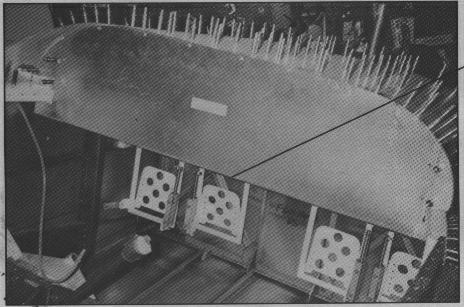 |
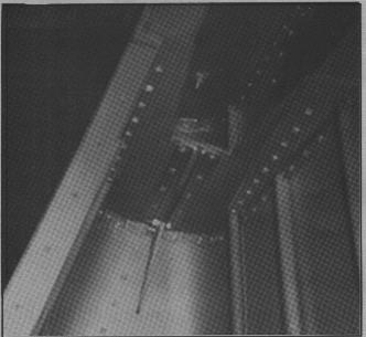
The centre console will end here, hinged to the panel. Then a piece will be fabricated to span from there to the F6105. And from F6105 to the 3/4 x 3/4 brace shown in drawing SC-2 Section A-A' near the firewall. This may just consist of one 3/4 x 3/4 brace from the hinged part of the firewall. |
 |
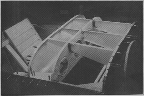
Except for 2 long curved pieces used to reinforce the 3/4 x 3/4 .063
angle that the panel attaches to. You know the one with all the notches
in it to allow for it to follow the panel curve.
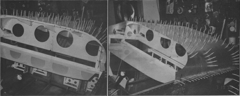
Except for that, these are the pieces I used to let the panel swing. Note the two panel 'end pieces' |
| This much can be removed and most rivets driven, then replaced on longerons. | 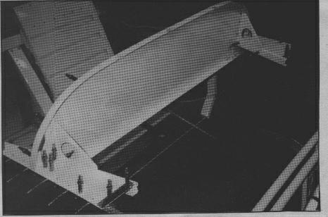 |
 |
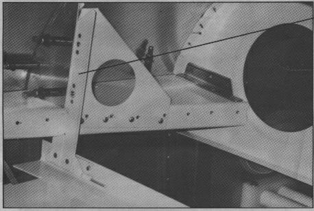
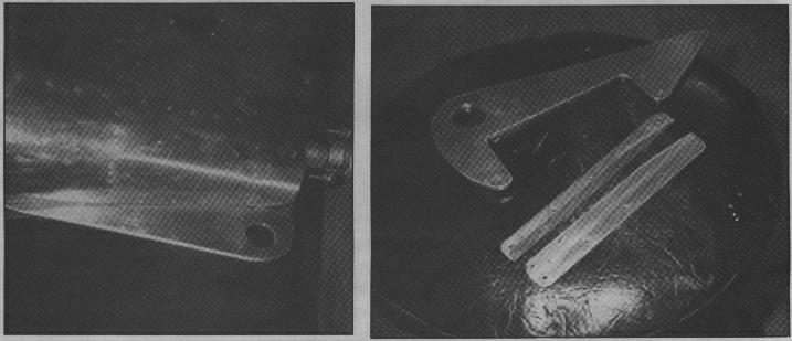
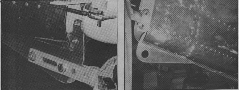
This is one of the 2 long curved pieces used to reinforce the 3/4 x 3/4 .063 angle that the panel attaches to. |
| This is part no. F6110. | 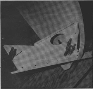 |
 |
Part A was made from extra material enclosed with the kit. It is left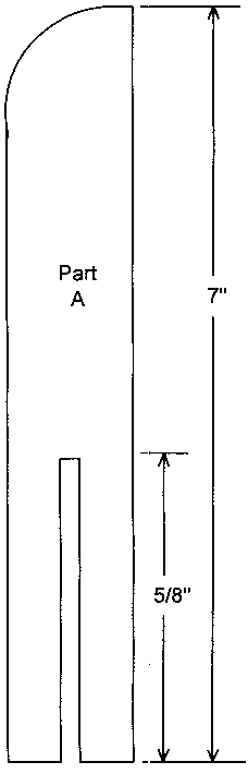 over from cutting spar strips. The slot in part A is for slipping over
the F6110 part.
over from cutting spar strips. The slot in part A is for slipping over
the F6110 part.
A slot was made in F6110 so the side wasn't cut out. The hinge pin will be secured. |
 |
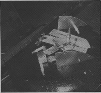
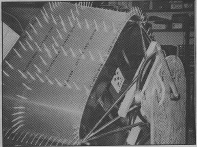
Radios and other long instruments will be 'racked' separately from
the panel itself.
The panel will have the smaller instruments fastened to the panel. |
 These
are the new parts.
These
are the new parts.
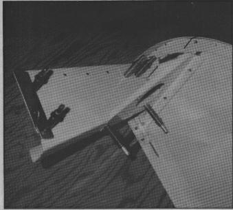
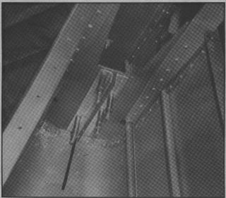 Inside braces in place. Notice the slot in skin.
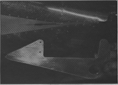 Shot of shape of part. Notice the slot in skin.
 Inside braces in place. Notice the slot in skin.
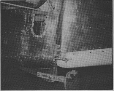
In left photo, notice where I had to take some metal out to leave room for the rudder.
They say a picture is worth a thousand words. Hmmm... 18,000 words and I'm not tired Yet.Email: cecilth@juno.com (805) 375-2660 |