This page consists of two articles copied from Jim Cone's Tri-State Newsletter relating to Jim's rudder trim system. The images were all created by Jim too.
While connecting the front of the rudder cables to the rudder pedals, I noticed three things that I didn't particularly like.
One was that the only way to adjust the rudder pedals was to make a new link between the cable end and the pedals. A link with more than one set of holes will allow only a small adjustment. I fixed this by making a "U" shaped fitting that attaches to the rudder cable end an an "L" shaped fitting that attaches to the rudder pedal. An AN-3 bolt connects the two. Now I can adjust my rudder pedal to any position just by changing the length of the bolt.
The second thing I didn't like was that as the rudder is moved through its full travel, the fitting on the end of the front of the cable makes a racket when it passed through the forward-most fairlead on the fuselage bulkhead. I fixed this problem by splitting a piece of tygon tubing long enough to reach from the end fitting to past the fairlead when rudder is as far forward as it can travel and wrapping it around the cable and end fitting I secured it with cable ties. Now it moves through the fairlead smoothly.
The third thing I didn't like was that the rudder cables were loose. By that I mean, there is no "run around" or return spring to keep the rudder cables taut. As designed, the rudder can slam from stop to stop in the breeze and possibly damage the rudder or the stops. I decided to install return springs in the system to keep the cables from from going slack and allowing the rudder to slam back and forth. As I was thinking of how to do this, I came up with the brilliant idea that if I was able to somehow bias the springs a bit, I could have a rudder trim sort of like the trim kit Vans sells for the aileron.
What I came up with is a cable that creates a run-around loop with springs attached between the cable and the rudder pedals. By turning the pulley that the cable wraps around, I can lengthen one cable while shortening the other, which in turn moves the centering force of the springs to apply some rudder in the direction desired. I made a second smaller pulley with a shaft attached to it so that I can have a two-to-one ratio for the control knob. I made a ratchet and spring stop so that when I want to move the rudder trim, I just push in the control knob and rotate it. When I release the knob, it locks in the new position. Noila! Two birds with one stone, and it only took three tries, the advice of three of my building buddies, and three and a half weeks of fiddling around with my metal lathe and milling machine to do it.
I have had a lot of requests for more information about my rudder trim system, so I decided to draw a sketch of it and describe how it works. The system came about because I did not like the fact that the rudder cables are not taut. When the rudder is displaced by the wind when the aircraft is parked, the cables can go slack and allow the rudder to bang against the stops as the wind changes. I also did not like the fact that the rudder trim as described in the plans only trims the rudder for one speed, presumably cruise speed for the most common flight condition. At all other speeds some rudder force is required to keep the plane in trim. I figured that if I put some springs attached to the rudder pedals, that would hold the cables tight and act to snub any wind blowing on the rudder.
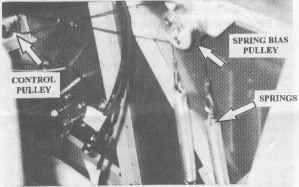
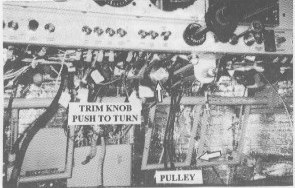
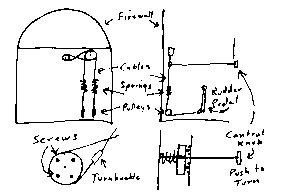
As I was figuring out how to hook them up I realised that if I could somehow bias the springs, that would allow me to pull on one rudder more than the other and thus act as a trim system, too. What I came up with is a system that uses cables attached to the passenger rudder pedals that run forward to the firewall, around pulleys that run the cables up the firewall. They then attach to springs which are again attached to cables that run up to another pulley. The cable from each rudder pedal is wound around the top pulley in opposite directions. I then added another pulley that allows me to turn that pulley to bias the rudder springs. That pulley has some cogs on the front side of it that allows it to lock in place by spring pressure. This prevents movement of the trim system until the pulley with the cogs on it is pushed away from the locking cogs and turned. I crossed the cable running from the control pulley to the spring pulley so that the trim control movement would be in the right direction for the desired trim. That is, clockwise for right trim, counterclockwise for left trim. I used aluminium for my pulleys but hardwood would work just as well. The cogs were made by using screws set 90 degrees apart. The control pulley is smaller than the spring pulley so that finer control is possible. I measured the rudder force at the trailing edge of the rudder. I came up with 40 pounds of force. That is more than enough to trim the rudder. I notice almost no difference in rudder pedal forces because the springs are working against each other at all times. The trimming force results from the different centre point when the springs are biased in one direction. I put a turnbuckle on the control cable because, as you can see in the picture, it is loose. Judging by the sketch, you know that I cannot draw, but I hope that it is clear enough to figure out. I'm sure that someone could come up with a simpler system, but this one works.