I'd decided beforehand to do the ailerons first, since they're more or less the same construction technique as the empennage control surfaces. I'll leave the spars, etc until later; ie until I've got some courage together! :-) This also delays the day when I need to move my workshop out of my spare room and into the garage (hopefully until after winter!).
Van's manual for wing building is not as good as for the empennage; I'd say that Frank Justice's manual is a must-have. Generally, I refer to this manual as FJ. However, since it was all written for non-prepunched, some doesn't apply. Even more useful is Will Cretsinger's notes... I refer to these as WC.
RV-List message posted by: Vince Himsl <vhimsl@turbonet.com>: Below are some 'extras' that I have bought while working on the wings.
1. Special #30 X 1/2 CounterSink Bit from Avery for the gas tank bolt attach points on the spar. Check their catalogue first but I think this is the correct description.
2. The tube type fluorescent light and telescoping mirror for looking inside the leading edge (often).
3. An offset 470AD4 rivet gun head with one side flattened for the leading edge ribs to spar attachment. I had an offset and flattened it on one side.
4. A hole saw or knock out punch @ 14mm to make a hole in each rib for the plastic conduit from Van's. Makes the hole just big enough to allow you to pull the conduit through and then hold it in place when you let it go.
5. Some sort of jack arrangement to keep centre of spar/rib assembly from sagging prior to installation of skins. I used the 1/4" bolts and blocks from the empennage inserted into each end of a wooden dowel (closet size, @1.5"). cost= $0.00
6. #6 and #8 dimple dies if you don't already have them. I also bought the #6 and #8 Counter Sink Bits. Used for access plates, gas tanks.
7. A rivet shaver for the 'crappy' gas tank rivet job. Don't ask me how I know (:>))
8. An inch-lb torque wrench. Used for tie down assembly and aileron control, empennage, etc.
9. #D, #19, #21(I think) drill bitts. Used on tanks, access plates.
10. I bought some NAS1097(?) 'ooops' rivets from Vans. I used them for 426AD3 spar holes that I had countersunk too deep.
11. The flaring tool from Avery Tools for the vent, gas, and pitot line AN type fittings. Read the plans regarding the dangers of inexpensive 45 degree flaring tools.
12. Angles, brackets, etc for modifying the empennage jig to hold the wing.
13. rose coloured glasses...self explanatory. (:>))
14. Paint booth/area. Mine is 4 x 6 x 7 feet made with 1x2 framing and cheap plastic($4.00 from Wal-Mart0.
For the tanks:
A wire brush bit for your cordless drill. (to score the tank
aluminium prior to applying sealant). Popsicle sticks, rubber gloves (throw
away kind, un powdered if you can get them), Lacquer Thinner, shop coat/overalls,
and an ice cream scoop for the pro seal from Vans (check archives for reference
to easier/costlier alternatives and finally balloons for the leak test.
Other:
Orndoff Video strongly recommended. He gives good treatment
of the gas tank construction process which is the biggest pain (I think)
of the wing though I found doing the gas cap flange and quick drain after
the stiffeners and inside ribs to be an easier sequence for me. Next
biggest pain is riveting the leading edge to the spar, especially the centre
ribs.
Completeness:
The wing kit is complete with everything except for the bolts and
nutplates that go to the gas sender (which you order separately).
I ordered the landing lights and wiring kit from Van's when I ordered the
Wing kit.
Joy, oh bliss... most of the spar stiffeners have already been tapered! And all the lightening holes have already been cut. Thank you, Vans! Sadly, the two longest stiffeners (W-606C) haven't been tapered yet.
It is worth it to taper the spar flange strips. Iit allows more space for you to install the nut plates for the fuel tank. There will be just a few that will be difficult to dimple. This is particularly true for the shortest of the stiffeners -- it's worth rounding the edges off near the end so that you can the end of your rivet squeezer in.
Note that the pre-drilled holes are off-centre by about 3/32"... if you taper the W-606C as per the plans (ie symmetrically) you won't have sufficient edge distance on the last rivet.
I cut the tapers on my my W-606Cs using a jigsaw. Clamp the end of the
W-606C to a piece of scrap wood (the piece I used was about 1" thick),
then cut through both the wood and the spar at the same time. A drop of
oil or kerosene on the cutting line was supposed to help, but didn't seem
to make much difference in my case. In fact, it was a bit of a pain because
sawdust stuck to it and obscured the line a little. Also, the Sharpie line
smudged a bit. ![]()
RV-List message posted by: jerry calvert <calverjl@flash.net>: I was putting the 1/4" radius on the end of all flanges and found an easy way to mark a nice 1/4" radius. If you bought the plastic buttons from Avery to run the string through to align your HS jig brackets, use them as a template to mark the radius. They fit the spar flange hole perfectly. Just pop it in and draw the radius around the button.
Be sure to examine the root end of each spar. There are marks engraved on the spar flanges that insure that you assemble the spar flanges back to their original positions. Copy these marks elsewhere on each piece -- they'll be almost illegible once primed.
Next step was to prepare the stiffeners for priming... what a dreary job. At least it was, until my friend Dave lent me his B&D power sanding block... a little palm-held orbital sander. Place a Scotchbrite pad on the stiffener, the gizmo on the pad, and turn it on. In no time at all, I'd cleaned up all the little scratches & pits.
Follow the FJ or WC notes as Vans manual is lacking in detail.
Be careful in drilling the 1/16" Al spreader angles. The spacings are
1" apart between the 5 innermost holes, and 1 3/32 between the outer &
next holes. The two closest to the all-important flange straps may be too
close to the ends. You may want to move them in toward the centre a little
to provide room to buck the rivets. ![]()
![]()
Be sure to chamfer (cut at 45 deg) the ends of 3/4 by 3/4 angles on the rear side of the spar to allow better access for riveting on the main skins. This also applies to the stiffener which attaches to the W-422 tie-down bracket -- it can interfere with riveting the LE skin to the spar.
This also applies to the stiffener between ribs 8 and 9 -- it aligns exactly with one of the nutplates which attach the fuel tank to the spar.
RV-List message posted by: COPANDENGR@aol.com: I noticed the proximity of the 1/2 inch hole to the spar web. I asked Van's about this and they assured me that this had not created any problems they were aware of, but to space the tie down out if it bothered me. I made a .125 inch spacer to fit between the bar and the web to bring the hole away from the radius.
RV-List message posted by: brietig@ibm.net: If you haven't already committed the hole in your spar flange, you might wish to mount the tie down attachment fitting to the front side of the spar. The RV-8 does it this way.
I had AN426AD4-11 and AN470AD4-11 rivets provided in my baggies, thus rendering Justice's rivet-cutting instructions redundant (except that I was one short on the flush ones, and I had to drill out and redo another one).
Be very generous in indexing all the spar parts with colour-coded markers. This will pay off big time as priming (even a thin layer of two-pot primer) makes factory engraving hard to see.
I trimmed the spar web ends first. I think that was a mistake... every time I moved the spar web around, the corners would dig into the ceiling or the wallpaper or something (don't try this at home if you have a spouse!).
Justice packs a lot of info in a few words. Case in point is #2 under "Making Spreader Angles..."
Be sure to countersink one side of spreader bar 5 (the 3/4x3/4 one)
to sink the shop heads into. The -22 rivets at spreader bar 5 didn't quite
fill the countersinks (normal size CS for 1/8" flush rivet) after I'd driven
them. That's normal, I think... I had a look at an RV-4 wing last weekend
and his are the same. There's a couple of 1/4" bolts holding things together
there too, so I don't think those rivets are critical. ![]()
When you are laying out the spreader bars, you can make sure you have them the right way up by laying down a couple of the flange strips.
FJ's "Adding the Flange Strips" #5 says to bolt the tie-down bracket
to the spar web. Don't use a locknut on the -12A bolt that goes through
the stiffeners... that'll have to be undone again later. ![]()
![]()
I'd hoped to skip the disassemble-and-reassemble step (all those holes are predrilled, right??), and forced rivets into some of the holes. Bad move! Several got stuck, and mashed when I pulled them out again. Be patient! You will need to pull it apart. Use one long rivet as a "tester" to make sure the holes line up nicely,, and if not, drill through with a #12. Better yet, after tightening up every 3/16 bolt in the spar, use a reamer to ream out every rivet hole. Every time you put the spar together, the holes will be just a little out of alignment.
Put rivets in every hole held in place with tape before you start riveting. ![]() You don't want to have to force a rivet into a hole or open out the hole
even more.
You don't want to have to force a rivet into a hole or open out the hole
even more.
FJ's The second-to-last sentence under #7 is a mystery. No way can you tighten up the close-tolerance hardware without the fuselage carry-thru hardware.
When it says to clean the primer out of the close-tolerance bolt holes, do it! Also, clean out any Scotchbrite dust and other rubbish. Those bolts are a very tight fit. You might want to use a little very light oil to ease them in.
I've been told that a regular 3 pound hand sledge worked great for pounding those spar rivets...4-5 medium-sized smacks, and George O seems to have no problem with a 3lb dead-blow hammer in the video. Practising on scrap, I found that a 3lb hammer wasn't heavy enough; twelve medium whacks, and often as not the rivet bent. I then used a 10lb (I guess) sledge, and two medium whacks with that, and the rivet's done.
Some extra ideas on using this technique:
* Set a hand mirror on the lower flat of the Avery tool to confirm that rivet head is in the set properly (it also helps in moving the tool to the next rivet).
* Be sure to periodically retighten the hardware holding the spar components together. Pounding loosens them right quick!
* Be sure there is enough weight for the spar to hold the rivet head securely in the rivet set.
* Use clamps wherever possible. A swivel-headed vise-grip is very useful here.
* Support the spar horizontally. You could build up some wooden risers to hold the spar at a level so that the rivet head nests in cup. What I did was use some foam rubber squabs to support the end of the spar. Put 30lb of ready-mix in bag on each side of Avery tool to support this.
* Use kneepads and earmuffs!
Just starting to rivet wing spar -6 rivets at outboard end of wing spar and using the Avery C tool. I am getting a slight gap (.020") between the W606A spar and the W606C web. Drilled out rivets and tried again using bolts through adjacent holes on each side of rivet to hold everything together, but still not happy with results.
--------------------------------------
Nine rv-list replies in 24 hours confirm this is a common and sometimes unnoticed problem occurring when riveting the outboard portion of wing spars with rivet gun, squeezer or Avery "C" tool.
The three items below gave me nice rivets with zero gap between the W606A & W606C at the rivet itself and a maximum of .003" gap at one midpoint between two reworked rivets (may be due to previous bending of W606C).
(1) Turn the rivet around so that the rivet factory head is on the thinner metal, opposite to plans, but OK'd with John @ Vans.
(2) Check adjustment/alignment of base block on the Avery C tool, use long shaft & 3/16 drill bit to align with hole in base block.
(3) Seat W606A spar and W606C web together after rivet is partially set.
Brian Eckstein gave me a clue when he recommended placing a 1/4" socket over rivet and tapping the socket to seat the pieces together, I refined this idea and made a seating block that works with the Avery C tool. Use a scrap piece of aluminium about 3/4" wide X 1" long and 3/4" thick, drill a 1/4" hole part way through the block to sit over a partially set rivet.
MY PROCEDURE FOR SETTING OUTBOARD WING -6 RIVETS
Using Avery C tool and 3 lb. hammer, one person operation. Place factory head of rivet in Avery C tool rivet set (use the 1.5" extension as required) make sure no protrusions keeps rivet from sitting firmly in rivet set. Level spar, tapered 2 X 4 lumber helps with small adjustments. Use clamps or bolts in holes adjacent to rivet to tie everything together.
One hard or two medium blows with hammer to expand rivet diameter and partially set rivet; raise C tool driver and place the aluminium seating block over rivet; lower driver and give one medium blow to top of seating block, this will drive parts together and the expanded rivet will hold parts together; remove seating block; finish setting rivet.
OTHER INFO
Three hard blows or 5 - 6 medium blows will set 3/16 rivet using 3 lb hammer 16" handle. No weights used to prevent spar bounce. Instead of buying Avery Base Support Block for C tool I used a hardwood block screwed under base. Rivet diameter increases about .010" when set.
RV-List message posted by: Mark McGee <FMark40@aol.com>: I'm using the Avery C-Frame Tool method and I needed a way that would allow me to do it without a helper. What I came up with is working great and may be of interest.
I simply clamped a small dolly of about 8 inches square to the spar using an appropriately sized wood spacer. It is situated at about two feet from the tip end and it rolls to me as I pull it. I use additional spacers to compensate for any deviation in floor level to ensure the arbor is normal to the spar.
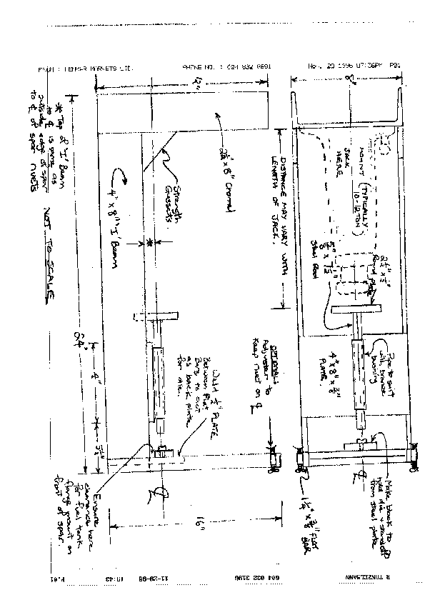
Another approach might be to use a press: here's a Spar Press design emailed to me by someone on the RV-list (can't recall who). You might even combine the press idea with the Avery tool.
Having said all the above, I didn't use the Avery tool. Instead, I got
a local A&P to help me. He came round with a 5X gun and large bucking
bar (although nowhere near the 7lb Vans recommends). ![]() Bucking the 3/16" rivets this way was not much more difficult that driving
1/8" rivets with a 3X gun. I know of two RV-4 builders who used 3X guns
to drive the 3/16" rivets. Although ultimately successful, they had problems
with work-hardening of the rivets.
Bucking the 3/16" rivets this way was not much more difficult that driving
1/8" rivets with a 3X gun. I know of two RV-4 builders who used 3X guns
to drive the 3/16" rivets. Although ultimately successful, they had problems
with work-hardening of the rivets. ![]()
According to the Avery rivet gauge, the -25 rivets were too long, so I cut them down to the "correct" length. When I drove them, the heads were too small! Do NOT cut down those long rivets! When I drove un-cutdown -25s I didn't have a problem, and the shop heads came out the right size.
Due to my problems with the Avery tool, I decided to drill out 10 of the long rivets. Think twice before embarking on this. Unless your rivets are REALLY bad, you are likely to make matters worse by drilling them out. My highly-experienced, semi-retired A&P assistant said: "I've never seen a rivet let go from being overdriven".
The technique I used: Drill off the head using the normal technique; 3/32" pilot, then 3/16" drill and snap off the head. Then drill a 3/32" hole down the centre (difficult with those long rivets) of the rivet to relieve its stress. Finally, use a 3/16" pin punch to drive out the rivet. Ensure that the spar on the other side is supported. I used a normal 20oz hammer, and it took a lot of hard hits to move the rivets.
On one of my drill-outs, I had the drill crooked, so I ended up with an out-of-round hole. We replaced that rivet with a longer one, cut to leave 2.5D protruding instead of the usual 1.5D. With some care, we drove that successfully. Therefore Van's comment in the manual that "Any more than the standard "1-1/2 D" extending out the holes, is asking for trouble", whilst true, doesn't mean you have to get it exactly right.
Note that the rib attachment holes (5/16" in, then 3 1/16" apart) are drilled but not riveted.
Be careful in the spacing of rivet holes on the W-607E inboard aileron doubler. Justice has you significantly enlarge the hole for the aileron pushrod and this may interfere with the top middle rivet. Draw the Justice-enlarged hole on the doubler at the time you mark rivet holes and possibly move the rivets nearest it. Actual location of these rivets does not appear critical.
I also cut these holes before riveting the doubler on; that allowed me to deburr the edges properly, and meant I couldn't get any little chips between doubler and spar. Pretty pointless really, since I needed to enlarge the hole a lot when I hung my ailerons. It would have been sensible to just drill a hole, maybe 3/4" diameter, as a starting point. The aileron pushrod will move in an odd pattern which requires a kidney-shaped (more or less) hole. Note that the W-607E doubler is shown on both pages 14 and 21 of the plans, with a slightly different riveting pattern!
I didn't put any rivets in the bottom holes attaching the doublers to the spar. This allowed me to back-drill through the spar into the gap seal -- WC's notes say to drill largish holes in the gap seal to allow for the heads of universal rivets. The back-drilled holes become pilots to centre the large holes. I think it would have been better to just use flush rivets for these rivets -- flush rivets are used for the bottom row of rivets attaching wing ribs to the rear spar.
Check the lengths of your W-607B & C stiffeners before rounding the ends; mine were 1.5" and .5" too long.
Instructions caution against making 2 left spars. Mark all rear spar
components as 'L' and 'R'. That way you'll have mirror images. There's
too many ways two parts can be put together; back-to-front, upside-down,
inside-out, so I sometimes add 'Top' or 'Front' labels. Nevertheless, I
still occasionally look at my rear spars and think "Ohmigod; I've put the
doublers on the wrong side, or cut the aileron pushrod hole on the bottom
instead of the top". I won't forget my gaffe with the elevators in a hurry. ![]()
Whilst cutting the W-607D plates out, you might as well cut out the FL-606B plates too.
Patrick Kelley <patk@mail.ic.net> wrote to the RV-list regarding the plumb-bob holes: The idea of measuring from the 0 station instead of from the tips is the key to getting the lateral alignment. After exhaustively remeasuring the spars currently in my jig, it is clear that one or the other of the spars is off by a fraction. The idea of making a marking jig would be icing on the cake, though I would not use my angle pieces for it. I would try to locate a strip of aluminium (my old employer would probably have a long enough piece, or maybe Van's could help) that I would index for the spar webs and mark both the rib locations and the alignment holes on. I'd try for a narrow strip (1 1/2") and flush rivet some stand-offs (so they'd swivel, like a feeler gauge) on for the the forward and rear spar differences). Then I'd sell it to everyone and retire <grin>. It would make marking easy enough to be worth the trouble and I wish I'd thought of it before, but thank heavens it wasn't necessary - my first wing came out fine and the second looks to be Ok, too.
Note also that the wing spar does NOT go between the flanges of the
F-604A. The spar is bolted to the front of the F-604A, while the flange
of the F-604A faces aft. This is clear from DWG 15 (with hindsight) --
I got it completely wrong originally, and had to drill the F-604A and C
apart again. Therefore you should countersink the non-flange side of the
F-604A.![]()
![]()
My F-604D pieces would only fit one way... the identifying marks go to the inside.
To align the F-604B and C pieces for drilling the 5/8" rudder cable holes, I placed 3/16" rivets in the holes and used side-grip clecos to hold them together.
When riveting the F604A and C pieces together, I used the 1/4" close-tolerance bolts for alignment. I also used 3/16" rivets. That wasn't a good idea, things moved a bit during riveting and I wound up drilling out 3 of the 3/16" rivets (No, I hadn't set them... I just couldn't pull them out the holes). On the other side, I used some 3/16" bolts... a much better idea.
The manual (or was it WC or FJ) calls for 3/32" rivets at 3" spacing to attach the F604D (the side plates which the spar fits through) to the C and B pieces (from memory -- I don't have the manual or notes or plans in front of me). The bottom and third rivet holes (there's no rivets installed) limited the placement of rivets for the F654 and F655 gussets. At this stage (fuselage skeleton construction) I don't see any reason why those holes needed to be drilled at all.
The RV-list abounds with people taking pieces of wood to a joiner to get planed down to within .002" of their spar thickness. And facing the false spar with al sheet. I didn't do all this fancy stuff.
Cut two pieces 22 1/2" long from one of the wing box sides for the two halves of the false spar. These will extend from the sides of the fuselage by about 5" each -- the idea is to use these to support the fuselage when it's finally out of the jig and turned right-side-up. These pieces will be too thin by about 3/8". So I nailed some 1/4" plywood and some 1/8" plywood to it around the area where the F604C will attach to it. This made it about the same as the spar itself. When I actually fit the false spar to the bulkhead, I use a couple of .032" al shims so that the gap is 1 1/4", slightly more than the thickness of the spar.
Also build up the false spar thickness to 1 1/4" at 11" from the centreline... there's a floor stiffener that will eventually attach to the spar here.
Finally, at 4" from the centreline, build it up to 2 1/4". There's another floor stiffener here, and the spar will be extra thick because the splice plates will be bolted to the front here.. However, this extra thickness needs to be removable, so that the false spar can be pulled out. I made this thickness out of another layer of box side, and a layer of 1/2" particle board. These layers are bolted on using some 3/16" bolts through the 3/8" holes in the spar.
Drill 3/16" holes through the existing 3/16" holes in the bulkhead to attach the false spar to it.
If you're going with manual trim (or feeding electric cables through the spar), cut a slot in the false spar from the location of the hole to the edge. This is so that the false spar can be removed after the trim cable has been installed.
Look at the photographs in the manual; they show quite clearly the rivet drilling pattern for the rib-spar attachment flanges.
I found Justice's hole-drilling instructions for the rib-spar attachment rivets incomprehensible; here's the simple version. For rib numbers, I use Justice's numbering system: rib 1 is the root, 14 is the tip. Rib 8A is the nose rib inboard of 9.
After reading some vague stories about problems running the wiring inside the fuselage to the usual place (back of the main spar) I decided that I was going to put mine in front of the main spar, between the tank rear baffle and the spar, then on through the LE ribs. Now, I don't think that was a good idea. The LE ribs have stiffeners riveted to them, so the conduit must be some distance (3/4" minimum) from the spar. Then, in the 1/2" or so between rib 8A and the outboard end of the tank baffle, it needs to get down to the spar. Obviously this involves some fairly sharp corners which means that pulling wire through after assembly will be extremely difficult, maybe even impossible after the fuel tanks are fitted. That in turn means I've missed one of my goals -- I wanted to make it fairly easy to add wires to the wings. Given all of this (and bearing in mind I haven't started the fuselage yet, so can't say how difficult it's going to be to run wires round the spar) I suggest putting the wiring conduit where WC recommends.
There are several possible locations, each has its pros and cons.
One possibility is right behind the spar, below the top of the wing. Each rib has a nice area there formed by the front flange, top flange, and fwd lightning hole. You can't run the conduit in the bottom of the wing that far fwd because then it will interfere with the access hole.
You can also run it through the ribs just aft of the aileron bellcrank area. Again, watch out for interference with the access hole if you run the conduit on the bottom.
Running the conduit through the ribs next to the bottom skins and a positioned a little farther aft is about the best location, I think. That way it can go into the fuselage right into the side of the seat ribs without a lot of bending.
The other thing to think about is that you would like the conduit to rest next to the skins (top vs bottom) that you rivet on FIRST. That way you can rivet the first set of skins on, install the conduit, and it will be out of the way when you rivet the second set of skins on.
To drill the holes neatly in a straight line, measure and drill a #40 pilot hole in the tip rib, which is reverse orientation to the rest. Then use a couple of 3/16" bolts or rivets through the tooling holes to hold this rib aligned with the next rib and drill through the pilot hole. Repeat for all ribs.
I used PVC pipe for my conduit. This was about 0.8" OD. I drilled the holes to .75" using a hole saw, then deburred and opened them out to 0.8" with a round file. The PVC can be bent a fair bit if necessary by heating it (e.g. a hair dryer or boiling water). For really sharp bends, I'll connect two PVC tubes with some flexible soft plastic conduit which fits over the outside of the PVC.
Don't actually install the conduit until the rest of the skeleton is complete. Otherwise it'll get in the way of the bolting and riveting.
To save on measuring, carefully measure the 5 hole positions on one rib (say T404L one). Drill these #40. Now put this rib (let's call it the master rib) web-to-web (back-to-back?) with a rib of the opposite side (T404R), and align them by putting 3/16" rivets through the tooling holes. Drill #40 through the first rib into the second. Drill the holes in the second rib the right size and check positioning. Mine were *perfect*, but if yours aren't make a new master and try again. Now use the master to drill all T404R ribs with #40 holes. Then, use one of those to drill all the other T404L ribs. Now, drill the 7/16" vent hole in each inboard T403 rib (one each (obviously!) of L & R) using your master ribs Note that GeorgeO in the video has drilled his lower (down inside the stiffening ring) on these inboard ribs (dunno why -- my plans definitely show them near the top). Finally, drill all the holes out to the right size.
The 1.5" holes at the rear bottom portion of the inner tank ribs are centred 7/8" up. A little math tells you the edge is 1/8" up from the bottom. These holes need to be cut as close as possible to the lower flange, otherwise they could result in water (or fuel!) being trapped between the ribs. Mine were perfect, but if they weren't I'd consider enlarging the hole downwards with a file. Alternatively, I see no reason why you couldn't drill a couple of extra 1/8" holes at the very bottom of the tank rib in the level flight attitude (to get that last drop of fuel) and in the 3-point attitude if building a -6 (to drain that last drop of water).
Following comments on the RV-list about slow filling of the last tank bay, I have drilled two more 1/4" vent holes near the top (in 3-point attitude since I'm building a -6) of rib 5.
Check the joggle at the rear of the rib; it goes to the bottom.
The .125 angle is to be cut from one of the 10'10" pieces; despite the label on them, they're not used for the firewall, which is now all pre-cut according to Vans.
FJ calls for several holes to be predrilled on the 1/8" angles. Check the position of these holes relative to the tooling hole and lightening hole in the rib. You may want to move them a bit to provide more clearance. Mark centrelines of those .125 angles on the BC assembly on the other side of the rib. This will tell you real quick if that hole you are about to drill is going to have proper edge distance.
Rearward of the lightening hole, there are 3 * 1/8" rivets attaching the 1/8" angles to the rib. Drill all three holes, but do not rivet the one that will later attach to the W-425 bellcrank gusset -- the front one. This last hole will be used as a pilot to attach the W-425, so perhaps only drill it #40.
Note that the diagram bottom-left of Plan 19a (Section A-A) is (I think) wrong... it shows a flange rearward of the W-425 attaching it to the rib. An arrow identifies this flange as "W-425 Rib". This flange doesn't exist... both the flanges at the ends of W-425 face forward.
The two .125 angles sit on a .063 angle at the aft end of this assembly. Plans call for rivets an inch or so forward of where the angles are riveted together. Problem is there is about .063 space between rib web and .125 angle. I didn't worry about this; the rib pulled to the .125 angle OK.
Alternatively, durbanski@juno.com (Daniel R Urbanski) wrote to the RV-list: If you look at the assembly picture of the bell crank in the manual you will see that the two .125 angles have been relieved .063 deep and back just enough, so that the angles will make contact with the rib. If you do this make sure you leave a generous radius where you remove the material.
I cut the slot between the lightening holes pretty much all the way back to the .125 angles.
Look at the photographs in the construction manual; you may want to
taper the 1/8" bellcrank support angles. I did! This tapering is not mentioned
in the plans at all, so you'll need to guesstimate dimensions. ![]()
Whilst working in this area, I thought I'd build the bellcranks as well. That worked out OK, but to keep this Guide more-or-less aligned with WC's notes, I've put bellcrank construction in the 'Ailerons and Flaps' section.