 |
Matronics Email Lists
Web Forum Interface to the Matronics Email Lists
|
| View previous topic :: View next topic |
| Author |
Message |
galinhdz(at)gmail.com
Guest
|
 Posted: Tue May 05, 2015 12:25 pm Post subject: Help on this situation. Posted: Tue May 05, 2015 12:25 pm Post subject: Help on this situation. |
 |
|
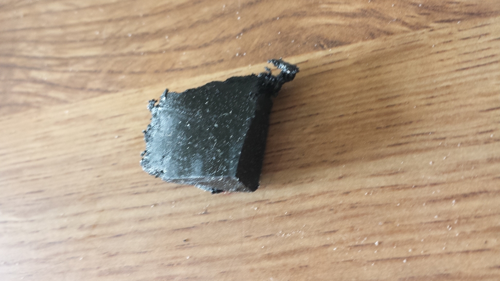
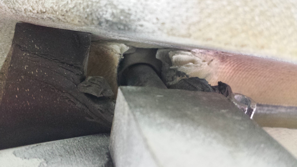
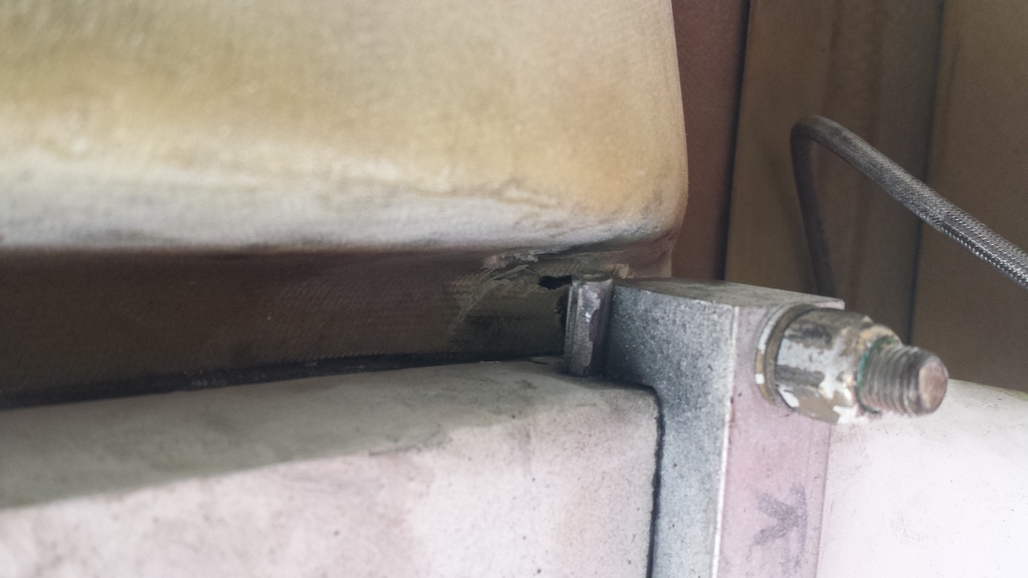
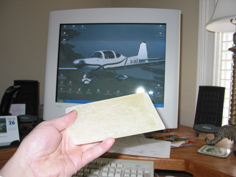
While cleaning the underbelly of my airplane I noticed a small piece of 1/4" thick hard rubber near where the right main landing gear attaches to the fuselage. (Photo1)
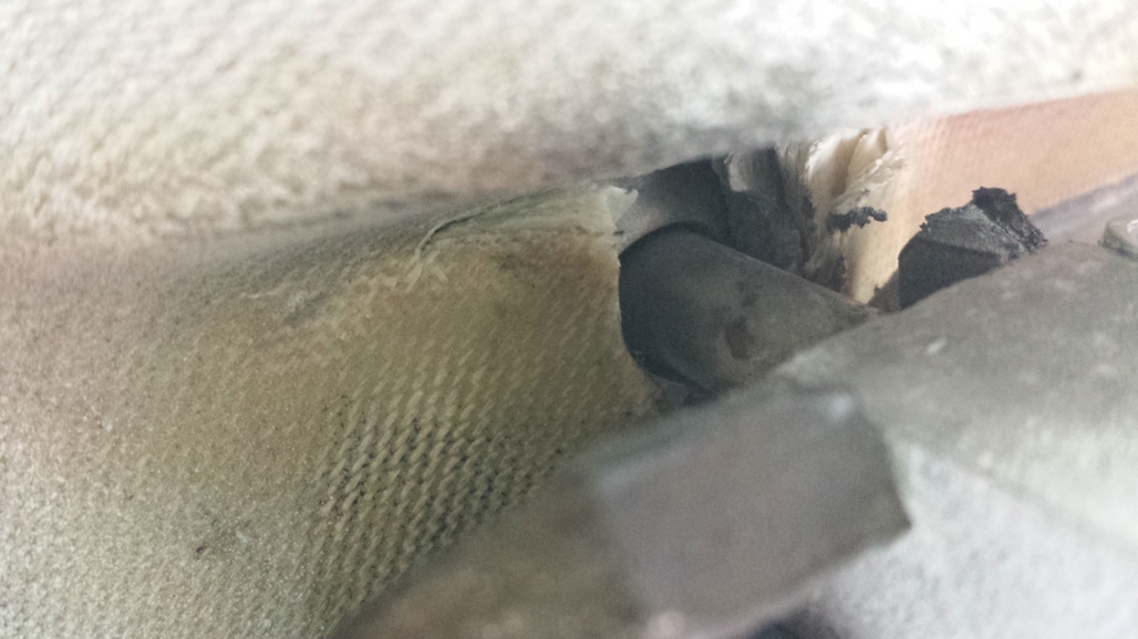
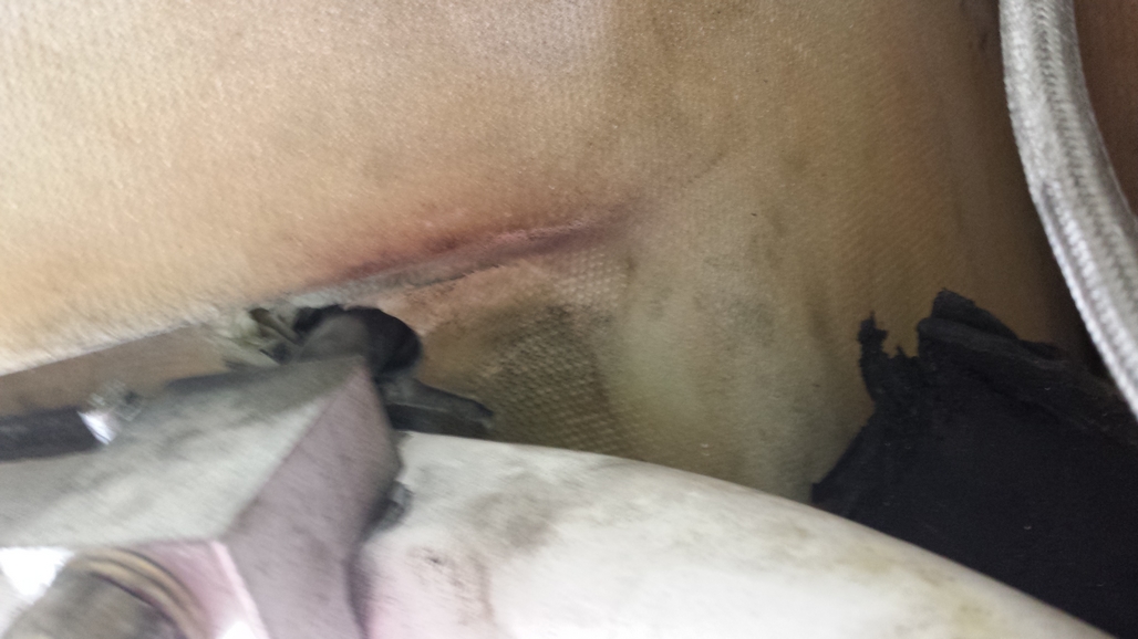
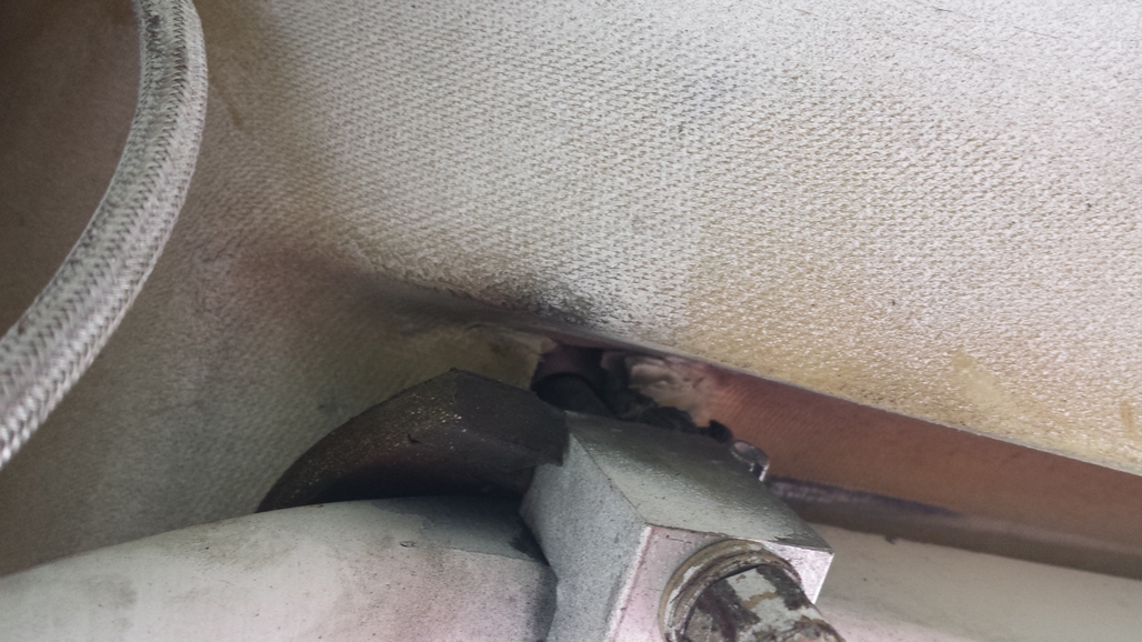
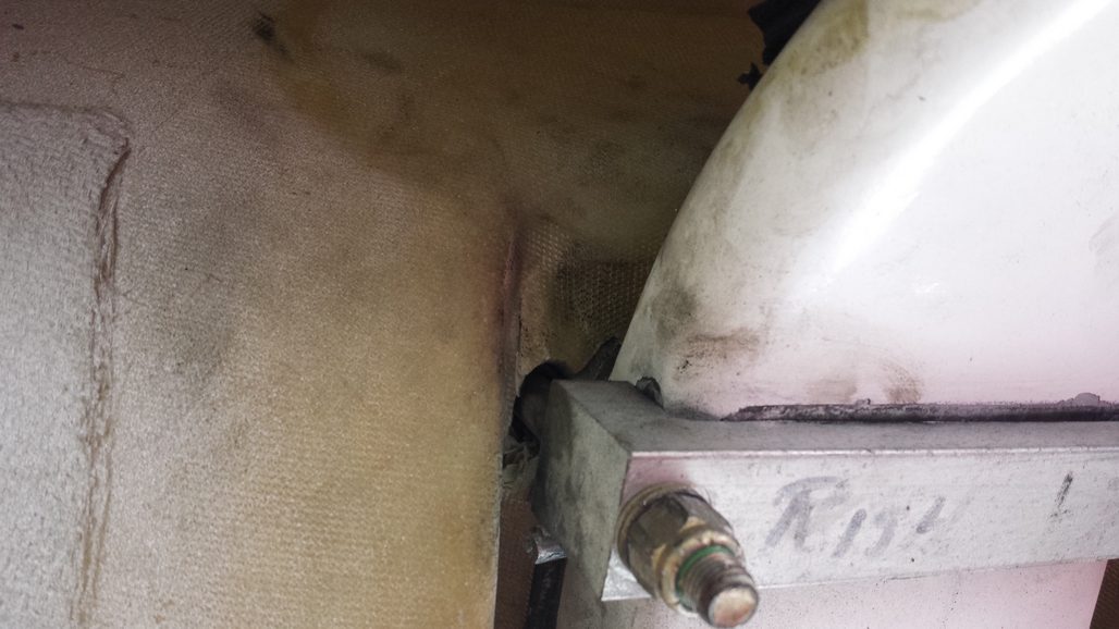
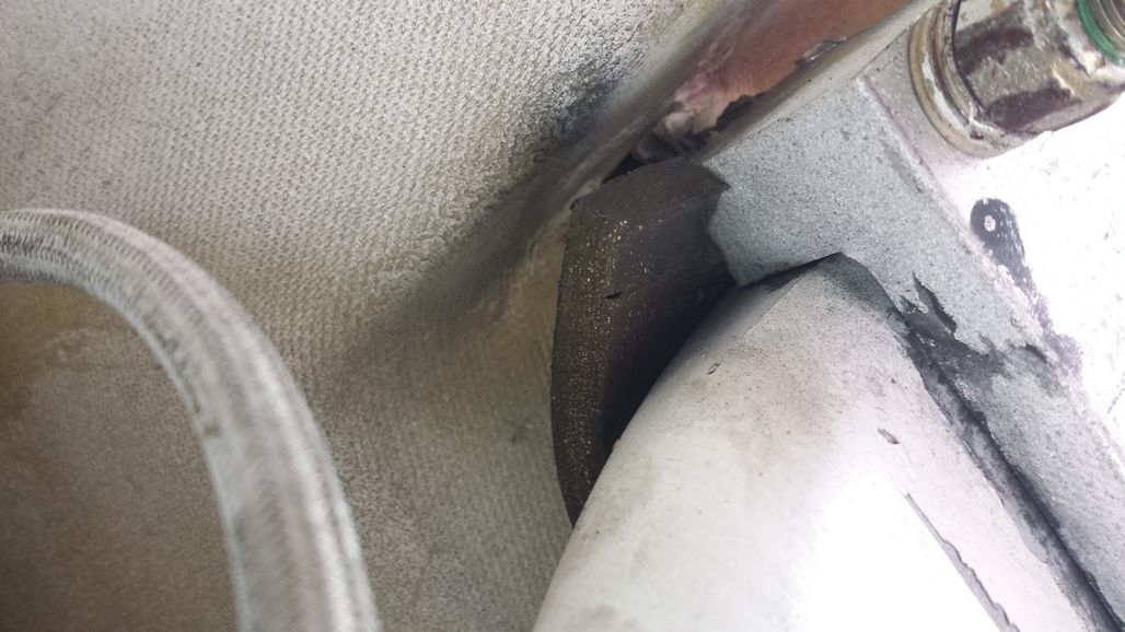
I took off all the inspection panels and found that the 1/4" thick hard rubber piece that goes between the landing gear and the fuselage had ripped with the piece I found falling out. I also noted that the fiberglass around the front hole where the bolt enters the fuselage is cracked. (Photos 2-3)
I checked the left great attachment and the rubber has not ripped but the fiberglass around the front hole where the bolt enters the fuselage is also cracked. (Photos 5-6)
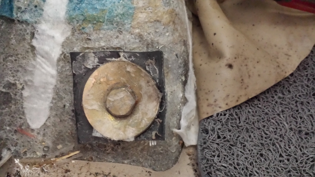
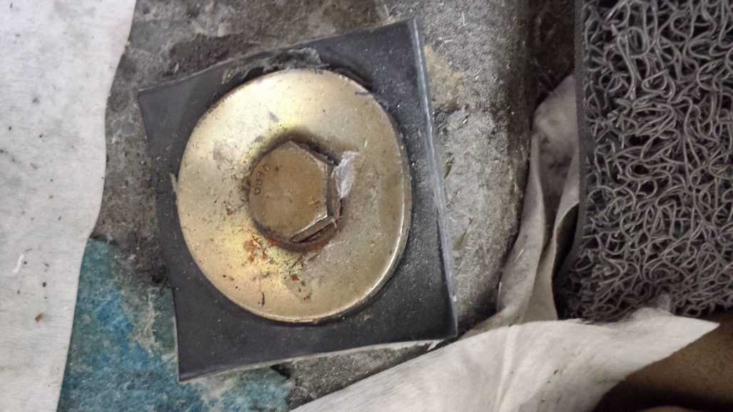
The top part of both bolts inside the fuselage look the same as they have been during every condition inspection. (photos 4 & 7)
Not being a fiberglass guy my question is this a safety of flight issue? I am not flying the airplane until I get a better idea of what I am up against.
Any help/recommendations are very welcome. No matter what, I will have to get someone nearby to fix this for me since again, I am not a fiberglass guy.
| | - The Matronics KIS-List Email Forum - | | | Use the List Feature Navigator to browse the many List utilities available such as the Email Subscriptions page, Archive Search & Download, 7-Day Browse, Chat, FAQ, Photoshare, and much more:
http://www.matronics.com/Navigator?KIS-List |
|
| Description: |
|
| Filesize: |
391.97 KB |
| Viewed: |
16389 Time(s) |
|
| Description: |
|
| Filesize: |
347.64 KB |
| Viewed: |
16390 Time(s) |
|
| Description: |
|
| Filesize: |
329.3 KB |
| Viewed: |
16389 Time(s) |
|
| Description: |
|
| Filesize: |
388.75 KB |
| Viewed: |
16389 Time(s) |
|
| Description: |
|
| Filesize: |
350.37 KB |
| Viewed: |
16389 Time(s) |
|
| Description: |
|
| Filesize: |
463.5 KB |
| Viewed: |
16389 Time(s) |
|
| Description: |
|
| Filesize: |
477.64 KB |
| Viewed: |
16389 Time(s) |
|
|
|
| Back to top |
|
 |
aeromomentum(at)yahoo.com
Guest
|
| Posted: Tue May 05, 2015 1:20 pm Post subject: Help on this situation. |
|
|
Not a problem for flying.


But it could be a big problem on landing.


I would not fly until this is fixed.


There really needs to be a larger and stronger washer on the top and preferably a real backing plate on top of a perfectly flat area on gear box.  This area actually is below part 23 required strength even if done perfectly to the builder's manual.  Even the AN6 bolt is loaded a bit more than I like in a critical application but does have a +0.17 margin of safety.


To me it looks like there is obvious damage to the fiberglass at the tops of the bolts even beyond the washers. I am sure it is worse under the washers. Also the washers have been overloaded since they are now greatly dished.  If you have any dishing of these washers you are overloading them and you need to correct this to prevent damage to the fiberglass and inspect under the washers to make sure there is no damage.


Mark Kettering


--------------------------------------------

On Tue, 5/5/15, Galin Hernandez <galinhdz(at)gmail.com> wrote:


 Subject: Help on this situation.

 To: "kis-list(at)matronics.com" <kis-list(at)matronics.com>

 Date: Tuesday, May 5, 2015, 4:24 PM


 While cleaning

 the underbelly of my airplane I noticed a small piece of

 1/4" thick hard rubber near where the right main

 landing gear attaches to the fuselage. (Photo1)

 I took off all the inspection panels and found

 that the 1/4" thick hard rubber piece that goes between

 the landing gear and the fuselage had ripped with the piece

 I found falling out. I also noted that the fiberglass around

 the front hole where the bolt enters the fuselage is

 cracked. (Photos 2-3)

 I checked the left great attachment and the

 rubber has not ripped but the fiberglass around the front

 hole where the bolt enters the fuselage is also cracked.

 (Photos 5-6)

 The top part of both bolts inside the fuselage

 look the same as they have been during every condition

 inspection. (photos 4 & 7)

 Not being a fiberglass guy my question is this a

 safety of flight issue? I am not flying the airplane until I

 get a better idea of what I am up against.

 Any help/recommendations are very welcome. No

 matter what, I will have to get someone nearby to fix this

 for me since again, I am not a fiberglass guy.
| | - The Matronics KIS-List Email Forum - | | | Use the List Feature Navigator to browse the many List utilities available such as the Email Subscriptions page, Archive Search & Download, 7-Day Browse, Chat, FAQ, Photoshare, and much more:
http://www.matronics.com/Navigator?KIS-List |
|
|
|
| Back to top |
|
|
fredorosa(at)gmail.com
Guest
|
| Posted: Tue May 05, 2015 2:17 pm Post subject: Help on this situation. |
|
|
Not usable as is. Â You need to beef up the whole recessed gear channel with carbon fiber layups.And preferably at the nut end of the bolts also. Â My 3 cents.
On Tue, May 5, 2015 at 4:24 PM, Galin Hernandez <galinhdz(at)gmail.com (galinhdz(at)gmail.com)> wrote:
[quote]While cleaning the underbelly of my airplane I noticed a small piece of 1/4" thick hard rubber near where the right main landing gear attaches to the fuselage. (Photo1)
I took off all the inspection panels and found that the 1/4" thick hard rubber piece that goes between the landing gear and the fuselage had ripped with the piece I found falling out. I also noted that the fiberglass around the front hole where the bolt enters the fuselage is cracked. (Photos 2-3)
I checked the left great attachment and the rubber has not ripped but the fiberglass around the front hole where the bolt enters the fuselage is also cracked. (Photos 5-6)
The top part of both bolts inside the fuselage look the same as they have been during every condition inspection. (photos 4 & 7)
Not being a fiberglass guy my question is this a safety of flight issue? I am not flying the airplane until I get a better idea of what I am up against.
Any help/recommendations are very welcome. No matter what, I will have to get someone nearby to fix this for me since again, I am not a fiberglass guy.
[b]
| | - The Matronics KIS-List Email Forum - | | | Use the List Feature Navigator to browse the many List utilities available such as the Email Subscriptions page, Archive Search & Download, 7-Day Browse, Chat, FAQ, Photoshare, and much more:
http://www.matronics.com/Navigator?KIS-List |
|
|
|
| Back to top |
|
|
flyinisfun90(at)gmail.com
Guest
|
| Posted: Tue May 05, 2015 2:38 pm Post subject: Help on this situation. |
|
|
Galin,Alfred is right in my opinion. That bolt came too close to the edge of the box to satisfy me and could not seat squarely on the surface. I built it out, lapping it over the top until there was a good flat seat for the washer to set on. All built up layers should go out onto the skin surface at least 2 inches. Probably taper them off as they run out. Don't stack them up as this will cause a very stiff edge that will tear loose quicker. By the time the repair is completed they will have lapped out some 3 inches, front side and back side. Mud the washer back in with an epoxy and flox mix. My 2 cents worth is to use at least 12 layers and keep a close eye on it as landings build. Probably run the patch some 12 inches long on each area. Â
  Jesse Wright
PS  OC would also be a good source for advice. Good Luck.   Â
On Tue, May 5, 2015 at 4:16 PM, Alfred Rosa <fredorosa(at)gmail.com (fredorosa(at)gmail.com)> wrote:
[quote]Not usable as is. Â You need to beef up the whole recessed gear channel with carbon fiber layups.And preferably at the nut end of the bolts also. Â My 3 cents.
On Tue, May 5, 2015 at 4:24 PM, Galin Hernandez <galinhdz(at)gmail.com (galinhdz(at)gmail.com)> wrote:
| Quote: | While cleaning the underbelly of my airplane I noticed a small piece of 1/4" thick hard rubber near where the right main landing gear attaches to the fuselage. (Photo1)
I took off all the inspection panels and found that the 1/4" thick hard rubber piece that goes between the landing gear and the fuselage had ripped with the piece I found falling out. I also noted that the fiberglass around the front hole where the bolt enters the fuselage is cracked. (Photos 2-3)
I checked the left great attachment and the rubber has not ripped but the fiberglass around the front hole where the bolt enters the fuselage is also cracked. (Photos 5-6)
The top part of both bolts inside the fuselage look the same as they have been during every condition inspection. (photos 4 & 7)
Not being a fiberglass guy my question is this a safety of flight issue? I am not flying the airplane until I get a better idea of what I am up against.
Any help/recommendations are very welcome. No matter what, I will have to get someone nearby to fix this for me since again, I am not a fiberglass guy.
et="_blank">http://www.matronics.com/Navigator?KIS-List
tp://forums.matronics.com
_blank">http://www.matronics.com/contribution
|
[b]
| | - The Matronics KIS-List Email Forum - | | | Use the List Feature Navigator to browse the many List utilities available such as the Email Subscriptions page, Archive Search & Download, 7-Day Browse, Chat, FAQ, Photoshare, and much more:
http://www.matronics.com/Navigator?KIS-List |
|
|
|
| Back to top |
|
|
mark_trickel
Joined: 13 Dec 2011
Posts: 101
Location: Philadelphia, PA, USA
|
| Posted: Wed May 06, 2015 8:43 am Post subject: Re: Help on this situation. |
|
|
Hello Galin,
Once again you are on the fringes of the unknown. With 1000 plus hours I can only guess you have at least 2000 landings (maybe more) on the airframe.
Your pictures tell a very compelling story, and there are no hidden secrets. If I were inspecting your airplane, and saw the washers now in a concave mode I would immediately throw up a red flag. Looking farther, and noticing the washers under the bolts show a lot of wear. Either bolt bolts are spinning around in the holes or somebody has been tightening them as they became lose.
Mark is right the story under those washers is not going to be pretty. All the glass, and resin under the washers is now completely crushed!
Loads on the main gear-
When the landing gear touches the runway the forces are tremendous. You have the rate of decent, and the forward momentum of the airplane all converging at once on those two tiny little bolts on the front end of the main gear attach brackets. Just imagine the TR-4 near gross weight say 2300 pounds with a bunch of fuel burned off (oh right, some builders keep increasing the gross weight, what am I thinking) heading towards the runway at 70 plus miles per hour. There may be wheels attached to the end of the landing gear leg but the moment it all touches the runway the forces at hand want to rip the landing gear off the airframe. And that is quiet evident form the pictures posted - a few more landing and the bolts would have won. Try googling forces on the main landing gear, and you will find the engineering formulas are very intense. Itâs a long subject better left to smart engineers. Needless to say the set-up we use on our KIS aircraft have room for improvement
I referred to the TR-4 manual â The set-up used on THIS installation is NOT correct. According to the manual Fuselage section 2, page 23. There is supposed to be a ¼ rudder spacer under the fender washer. What is shown in the pics are a very thin piece of rubber. That said, even if it did have the proper ¼â rudder under the washer I do not think it would have prevented this occurrence. The way it is set-up we are trying to place all the landing loads under the two forwards washers, and the loads are much too concentrated. The loads need to be spread out farther on each side where the gear attaches.
Another thing that would help is a much larger washer, and one or two smaller washers in the stack to support the larger washers (a certified airplane is allowed 3 washers in the stack). Possibly even using a piece of 4130 steel plate connecting to the rear bolt as well. My TR-1 has a ¼â X 1â bar that connects both bolts together. The ultimate set-up would be using two bolt spaced a last 1 ½â apart on the forward main landing gear attachment (would require a special custom attach bracket (would be worth the price of admission)). That would spread the load farther out, and really add a sense of security to landing operations, something every pilot needs. Another idea would be to add a rubber piece on the bottom side of the landing gear between the gear and the attach bracket. That would allow for more movement of the main gear The idea of putting rubber under the washer in the stack and cinching up on it makes no sense in me, putting rubber on both side of the gear seems like a much smarter way to go.
Doing the composite repairs is not difficult but I do not see any way around supporting the airplane, and dropping the main gear away. While the fiberglass repairs could be solely done from the inside of the cockpit, I think I would want to add plies to the underside of the affected areas, but you would have to be careful around the flox wedge that cants the main gear forward. Typically you need to v- out the cracks and scarf the edges and give it plenty of room for the patches to attach to (8 to 1 scarf should be good â use a dremel grinder and 80 grit sand paper to prep for glass). You only need to overlap the crack line by 2 inches on each side for a good repair. I would think about 20 to 30 layers of 10 oz. cloth would do, with 6 to 8 plies on the underside.
My2 cent Mark T
| | - The Matronics KIS-List Email Forum - | | | Use the List Feature Navigator to browse the many List utilities available such as the Email Subscriptions page, Archive Search & Download, 7-Day Browse, Chat, FAQ, Photoshare, and much more:
http://www.matronics.com/Navigator?KIS-List |
|
|
|
| Back to top |
|
|
fredorosa(at)gmail.com
Guest
|
| Posted: Wed May 06, 2015 9:27 am Post subject: Help on this situation. |
|
|
These radius blocks from GROVE are what I installed. The curved surfaces allow the aluminum gear to flex easily and not stress the bolts.
On Wed, May 6, 2015 at 12:43 PM, mark_trickel <marktrickel(at)gmail.com (marktrickel(at)gmail.com)> wrote:
| Quote: | --> KIS-List message posted by: "mark_trickel" <marktrickel(at)gmail.com (marktrickel(at)gmail.com)>
Hello Galin,
Once again you are on the fringes of the unknown. With 1000 plus hours I can only guess you have at least 2000 landings (maybe more) on the airframe.
Your pictures tell a very compelling story, and there are no hidden secrets. If I were inspecting your airplane, and saw the washers now in a concave mode I would immediately throw up a red flag. Looking farther, and noticing the washers under the bolts show a lot of wear. Either bolt bolts are spinning around in the holes or somebody has been tightening them as they became lose.
Mark is right the story under those washers is not going to be pretty. All the glass, and resin under the washers is now completely crushed!
Loads on the main gear-
When the landing gear touches the runway the forces are tremendous. You have the rate of decent, and the forward momentum of the airplane all converging at once on those two tiny little bolts on the front end of the main gear attach brackets. Just imagine the TR-4 near gross weight say 2300 pounds with a bunch of fuel burned off (oh right, some builders keep increasing the gross weight, what am I thinking) heading towards the runway at 70 plus miles per hour. There may be wheels attached to the end of the landing gear leg but the moment it all touches the runway the forces at hand want to rip the landing gear off the airframe. And that is quiet evident form the pictures posted - a few more landing and the bolts would have won. Try googling forces on the main landing gear, and you will find the engineering formulas are very intense. Itâs a long subject better left to smart engineers. Needless to say the set-up we use on our KIS aircraft have room for improvement
I referred to the TR-4 manual â The set-up used on THIS installation is NOT correct. According to the manual Fuselage section 2, page 23. There is supposed to be a ¼ rudder spacer under the fender washer. What is shown in the pics are a very thin piece of rubber. That said, even if it did have the proper ¼â rudder under the washer I do not think it would have prevented this occurrence. The way it is set-up we are trying to place all the landing loads under the two forwards washers, and the loads are much too concentrated. The loads need to be spread out farther on each side where the gear attaches.
Another thing that would help is a much larger washer, and one or two smaller washers in the stack to support the larger washers (a certified airplane is allowed 3 washers in the stack). Possibly even using a piece of 4130 steel plate connecting to the rear bolt as well. My TR-1 has a ¼â X 1â bar that connects both bolts together. The ultimate set-up would be using two bolt spaced a last 1 ½â apart on the forward main landing gear attachment (would require a special custom attach bracket (would be worth the price of admission)). That would spread the load farther out, and really add a sense of security to landing operations, something every pilot needs. Another idea would be to add a rubber piece on the bottom side of the landing gear between the gear and the attach bracket. That would allow for more movement of the main gear The idea of putting rubber under the washer in the stack and cinching up on it makes no sense in me, putting rubber on both side of the gear se!
 ems like a much smarter way to go.
Doing the composite repairs is not difficult but I do not see any way around supporting the airplane, and dropping the main gear away. While the fiberglass repairs could be solely done from the inside of the cockpit, I think I would want to add plies to the underside of the affected areas, but you would have to be careful around the flox wedge that cants the main gear forward. Typically you need to v- out the cracks and scarf the edges and give it plenty of room for the patches to attach to (8 to 1 scarf should be good â use a dremel grinder and 80 grit sand paper to prep for glass). You only need to overlap the crack line by 2 inches on each side for a good repair. I would think about 20 to 30 layers of 10 oz. cloth would do, with 6 to 8 plies on the underside.
My2 cent Mark T
Read this topic online here:
http://forums.matronics.com/viewtopic.php?p=441806#441806
===========
List" target="_blank">http://www.matronics.com/Navigator?KIS-List
===========
FORUMS -
_blank">http://forums.matronics.com
===========
b Site -
     -Matt Dralle, List Admin.
target="_blank">http://www.matronics.com/contribution
===========
|
| | - The Matronics KIS-List Email Forum - | | | Use the List Feature Navigator to browse the many List utilities available such as the Email Subscriptions page, Archive Search & Download, 7-Day Browse, Chat, FAQ, Photoshare, and much more:
http://www.matronics.com/Navigator?KIS-List |
|
| Description: |
|
| Filesize: |
238.81 KB |
| Viewed: |
16370 Time(s) |
|
|
|
| Back to top |
|
|
galinhdz(at)gmail.com
Guest
|
| Posted: Wed May 06, 2015 10:31 am Post subject: Help on this situation. |
|
|
I didn't get Mark K's reply but reading Mark T's reply I realize this is worse than I originally thought. Here are some more photos of the affected areas.
Does anybody know of somebody that I can pay to do the repairs. I don't feel comfortable doing these kinds of repairs.
On Wed, May 6, 2015 at 12:43 PM, mark_trickel <marktrickel(at)gmail.com (marktrickel(at)gmail.com)> wrote:
| Quote: | --> KIS-List message posted by: "mark_trickel" <marktrickel(at)gmail.com (marktrickel(at)gmail.com)>
Hello Galin,
Once again you are on the fringes of the unknown. With 1000 plus hours I can only guess you have at least 2000 landings (maybe more) on the airframe.
Your pictures tell a very compelling story, and there are no hidden secrets. If I were inspecting your airplane, and saw the washers now in a concave mode I would immediately throw up a red flag. Looking farther, and noticing the washers under the bolts show a lot of wear. Either bolt bolts are spinning around in the holes or somebody has been tightening them as they became lose.
Mark is right the story under those washers is not going to be pretty. All the glass, and resin under the washers is now completely crushed!
Loads on the main gear-
When the landing gear touches the runway the forces are tremendous. You have the rate of decent, and the forward momentum of the airplane all converging at once on those two tiny little bolts on the front end of the main gear attach brackets. Just imagine the TR-4 near gross weight say 2300 pounds with a bunch of fuel burned off (oh right, some builders keep increasing the gross weight, what am I thinking) heading towards the runway at 70 plus miles per hour. There may be wheels attached to the end of the landing gear leg but the moment it all touches the runway the forces at hand want to rip the landing gear off the airframe. And that is quiet evident form the pictures posted - a few more landing and the bolts would have won. Try googling forces on the main landing gear, and you will find the engineering formulas are very intense. Itâs a long subject better left to smart engineers. Needless to say the set-up we use on our KIS aircraft have room for improvement
I referred to the TR-4 manual â The set-up used on THIS installation is NOT correct. According to the manual Fuselage section 2, page 23. There is supposed to be a ¼ rudder spacer under the fender washer. What is shown in the pics are a very thin piece of rubber. That said, even if it did have the proper ¼â rudder under the washer I do not think it would have prevented this occurrence. The way it is set-up we are trying to place all the landing loads under the two forwards washers, and the loads are much too concentrated. The loads need to be spread out farther on each side where the gear attaches.
Another thing that would help is a much larger washer, and one or two smaller washers in the stack to support the larger washers (a certified airplane is allowed 3 washers in the stack). Possibly even using a piece of 4130 steel plate connecting to the rear bolt as well. My TR-1 has a ¼â X 1â bar that connects both bolts together. The ultimate set-up would be using two bolt spaced a last 1 ½â apart on the forward main landing gear attachment (would require a special custom attach bracket (would be worth the price of admission)). That would spread the load farther out, and really add a sense of security to landing operations, something every pilot needs. Another idea would be to add a rubber piece on the bottom side of the landing gear between the gear and the attach bracket. That would allow for more movement of the main gear The idea of putting rubber under the washer in the stack and cinching up on it makes no sense in me, putting rubber on both side of the gear se!
 ems like a much smarter way to go.
Doing the composite repairs is not difficult but I do not see any way around supporting the airplane, and dropping the main gear away. While the fiberglass repairs could be solely done from the inside of the cockpit, I think I would want to add plies to the underside of the affected areas, but you would have to be careful around the flox wedge that cants the main gear forward. Typically you need to v- out the cracks and scarf the edges and give it plenty of room for the patches to attach to (8 to 1 scarf should be good â use a dremel grinder and 80 grit sand paper to prep for glass). You only need to overlap the crack line by 2 inches on each side for a good repair. I would think about 20 to 30 layers of 10 oz. cloth would do, with 6 to 8 plies on the underside.
My2 cent Mark T
Read this topic online here:
http://forums.matronics.com/viewtopic.php?p=441806#441806
===========
List" target="_blank">http://www.matronics.com/Navigator?KIS-List
===========
FORUMS -
_blank">http://forums.matronics.com
===========
b Site -
     -Matt Dralle, List Admin.
target="_blank">http://www.matronics.com/contribution
===========
|
| | - The Matronics KIS-List Email Forum - | | | Use the List Feature Navigator to browse the many List utilities available such as the Email Subscriptions page, Archive Search & Download, 7-Day Browse, Chat, FAQ, Photoshare, and much more:
http://www.matronics.com/Navigator?KIS-List |
|
| Description: |
|
| Filesize: |
317.34 KB |
| Viewed: |
16369 Time(s) |
|
| Description: |
|
| Filesize: |
399.05 KB |
| Viewed: |
16369 Time(s) |
|
| Description: |
|
| Filesize: |
433.96 KB |
| Viewed: |
16369 Time(s) |
|
|
|
| Back to top |
|
|
bakerocb
Joined: 15 Jan 2006
Posts: 727
Location: FAIRFAX VA
|
| Posted: Wed May 06, 2015 1:51 pm Post subject: Help on this situation. |
|
|
5/6/2015
Hello Al, Thanks for your input. You wrote:
âThe curved surfaces allow the aluminum gear to flex easily and not stress the bolts.â
If the wheel axle is directly below the fore and aft center of the bolts and if the force applied to the wheel end of the landing gear is directly vertical, and therefore parallel to the bolts, then you are correct because the rotation of the landing gear crossbar around the curved surface of the radius blocks would cause minimal stress both along the length of the bolts nor in bending of the bolt.
But if the force applied to the wheel end of the landing gear has a fore-and-aft component to it then the attempted rotation of the crossbar will stress the bolts. And there is a significant aft component of force applied to the wheel end of the landing gear every time the non rotating tire comes into contact with the runway surface while the airplane is travelling at some significant forward speed.
Also if the landing gear is canted forward then even a directly vertical load parallel to the bolts at the wheel end of the landing gear will cause the aft edge of the crossbar to attempt to rotate downward and thereby place a longitudinal stress on the aft bolts.
I think that the radius blocks are very desirable, I just could not get the spacing to work our for my KIS TR-1 landing gear cross bar and the existing bolt hole locations.
OC
PS: Do you have some sort of thin elastomeric sheet between the top of the landing gear cross bar and the bottom of the fuselage flox bed that it fits up against? This is required to keep the relatively hard aluminum cross bar from crumbling any cured flox hot spots,
===============================================
From: Alfred Rosa (fredorosa(at)gmail.com)
Sent: Wednesday, May 06, 2015 1:26 PM
To: kisbuilders (kis-list(at)matronics.com)
Subject: Re: Re: Help on this situation.
These radius blocks from GROVE are what I installed. The curved surfaces allow the aluminum gear to flex easily and not stress the bolts.
[quote][b]
| | - The Matronics KIS-List Email Forum - | | | Use the List Feature Navigator to browse the many List utilities available such as the Email Subscriptions page, Archive Search & Download, 7-Day Browse, Chat, FAQ, Photoshare, and much more:
http://www.matronics.com/Navigator?KIS-List |
|
|
|
| Back to top |
|
|
galinhdz(at)gmail.com
Guest
|
| Posted: Thu May 07, 2015 4:29 am Post subject: Help on this situation. |
|
|
Al, which radius blocks did you use for your installation?
On Wednesday, May 6, 2015, Owen Baker <bakerocb(at)cox.net (bakerocb(at)cox.net)> wrote:
[quote] 5/6/2015
Â
Hello Al, Thanks for your input. You wrote:
Â
âThe curved surfaces allow the aluminum gear to flex easily and not stress the bolts.â
Â
If the wheel axle is directly below the fore and aft center of the bolts and if the force applied to the wheel end of the landing gear is directly vertical, and therefore parallel to the bolts, then you are correct because the rotation of the landing gear crossbar around the curved surface of the radius blocks would cause minimal stress both along the length of the bolts nor in bending of the bolt.
Â
But if the force applied to the wheel end of the landing gear has a fore-and-aft component to it then the attempted rotation of the crossbar will stress the bolts. And there is a significant aft component of force applied to the wheel end of the landing gear every time the non rotating tire comes into contact with the runway surface while the airplane is travelling at some significant forward speed.
Â
Also if the landing gear is canted forward then even a directly vertical load parallel to the bolts at the wheel end of the landing gear will cause the aft edge of the crossbar to attempt to rotate downward and thereby place a longitudinal stress on the aft bolts.
Â
I think that the radius blocks are very desirable, I just could not get the spacing to work our for my KIS TR-1 landing gear cross bar and the existing bolt hole locations.
Â
OC
Â
PS: Do you have some sort of thin elastomeric sheet between the top of the landing gear cross bar and the bottom of the fuselage flox bed that it fits up against? This is required to keep the relatively hard aluminum cross bar from crumbling any cured flox hot spots,
Â
===============================================
Â
From: [url=javascript:_e(%7B%7D,'cvml','fredorosa(at)gmail.com');]Alfred Rosa[/url]
Sent: Wednesday, May 06, 2015 1:26 PM
To: [url=javascript:_e(%7B%7D,'cvml','kis-list(at)matronics.com');]kisbuilders[/url]
Subject: Re: Re: Help on this situation.
Â
These radius blocks from GROVE are what I installed. The curved surfaces allow the aluminum gear to flex easily and not stress the bolts.
Â
| Quote: |
et="_blank">http://www.matronics.com/Navigator?KIS-List
tp://forums.matronics.com
_blank">http://www.matronics.com/contribution
|
[b]
| | - The Matronics KIS-List Email Forum - | | | Use the List Feature Navigator to browse the many List utilities available such as the Email Subscriptions page, Archive Search & Download, 7-Day Browse, Chat, FAQ, Photoshare, and much more:
http://www.matronics.com/Navigator?KIS-List |
|
|
|
| Back to top |
|
|
mark_trickel
Joined: 13 Dec 2011
Posts: 101
Location: Philadelphia, PA, USA
|
| Posted: Thu May 07, 2015 8:33 am Post subject: Re: Help on this situation. |
|
|
I am a fan of the radius blocks however these things do nothing to absorb the impact other than facilitating the flexing of the landing gear. If you use one of these blocks in the stack you will be narrowing the support area with which the landing gear has to operate within. We already have cracks and fiber crushing at the bolts I would not want to aggravate the situation by reducing the support area.
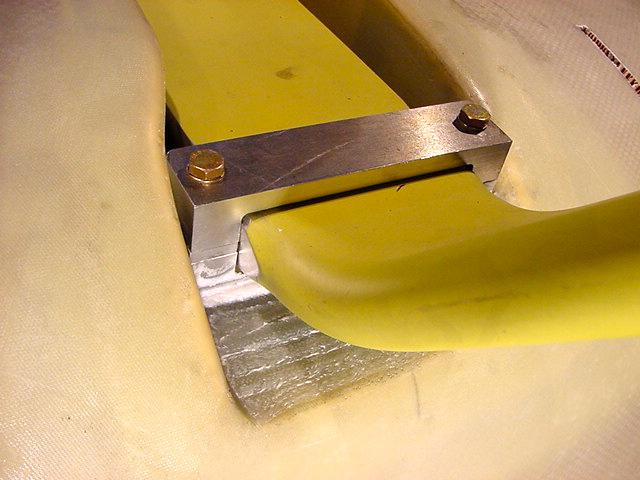
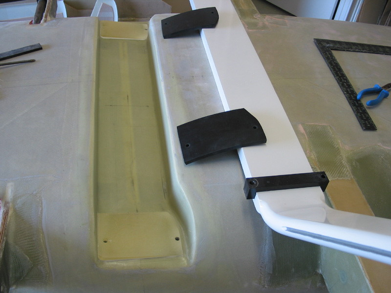
Attached are two pics from R Reeds site of Harry Herst's TR-4 showing the width of the surface involved here. You see how wide the Butyl rubber pad is - two or three time the width of the radius block. I am pretty sure the radius block were developed for metal airplanes. A radius block could be custom designed for the TR-4 but it would be much cheaper to add another layer of rubber if you were that concerned about the gear being able to flex. The other pic shows what a good wedge should look like.
Speaking of the main gear flexing...the term I use because I never considered aluminum to be springy - believe me these aluminum gears will flex a hellen. If you left the boots off, and hit hard enough you'd have black tire marks on the underside of the wings. Really!
OC - Unfortunately the recess for the landing gear on the TR-1 is too small and the gear will not fit within the space once it has been canted forward leaving out the possibility of a radius block....you would be surprised at the number of builds out there that do not have this vital modification!
| | - The Matronics KIS-List Email Forum - | | | Use the List Feature Navigator to browse the many List utilities available such as the Email Subscriptions page, Archive Search & Download, 7-Day Browse, Chat, FAQ, Photoshare, and much more:
http://www.matronics.com/Navigator?KIS-List |
|
| Description: |
|
| Filesize: |
698.91 KB |
| Viewed: |
16345 Time(s) |
|
| Description: |
|
| Filesize: |
95.29 KB |
| Viewed: |
16345 Time(s) |
|
|
|
| Back to top |
|
|
fredorosa(at)gmail.com
Guest
|
| Posted: Thu May 07, 2015 9:15 am Post subject: Help on this situation. |
|
|
Yes, OC suggested putting butyl rubber pads under the radius blocks
Which I intend to do.
Sent from my iPhone
| Quote: | On May 7, 2015, at 12:33 PM, "mark_trickel" <marktrickel(at)gmail.com> wrote:
I am a fan of the radius blocks however these things do nothing to absorb the impact other than facilitating the flexing of the landing gear. If you use one of these blocks in the stack you will be narrowing the support area with which the landing gear has to operate within. We already have cracks and fiber crushing at the bolts I would not want to aggravate the situation by reducing the support area.
Attached are two pics from R Reeds site of Harry Herst's TR-4 showing the width of the surface involved here. You see how wide the Butyl rubber pad is - two or three time the width of the radius block. I am pretty sure the radius block were developed for metal airplanes. A radius block could be custom designed for the TR-4 but it would be much cheaper to add another layer of rubber if you were that concerned about the gear being able to flex. The other pic shows what a good wedge should look like.
Speaking of the main gear flexing...the term I use because I never considered aluminum to be springy - believe me these aluminum gears will flex a hellen. If you left the boots off, and hit hard enough you'd have black tire marks on the underside of the wings. Really!
OC - Unfortunately the recess for the landing gear on the TR-1 is too small and the gear will not fit within the space once it has been canted forward leaving out the possibility of a radius block....you would be surprised at the number of builds out there that do not have this vital modification!
Read this topic online here:
http://forums.matronics.com/viewtopic.php?p=441838#441838
Attachments:
http://forums.matronics.com//files/tr_4_lg1_752.png
http://forums.matronics.com//files/tr_4_lg2_147.jpg
|
| | - The Matronics KIS-List Email Forum - | | | Use the List Feature Navigator to browse the many List utilities available such as the Email Subscriptions page, Archive Search & Download, 7-Day Browse, Chat, FAQ, Photoshare, and much more:
http://www.matronics.com/Navigator?KIS-List |
|
|
|
| Back to top |
|
|
galinhdz(at)gmail.com
Guest
|
| Posted: Thu May 07, 2015 1:22 pm Post subject: Help on this situation. |
|
|
Where is a good place to purchase some butyl rubber pads?


On Thursday, May 7, 2015, Alfred Rosa <fredorosa(at)gmail.com (fredorosa(at)gmail.com)> wrote:

[quote]--> KIS-List message posted by: Alfred Rosa <[url=javascript:;]fredorosa(at)gmail.com[/url]>


 Yes, OC suggested putting butyl rubber pads under the radius blocks

 Which I intend to do.


 Sent from my iPhone


 > On May 7, 2015, at 12:33 PM, "mark_trickel" <[url=javascript:;]marktrickel(at)gmail.com[/url]> wrote:

 >

 > --> KIS-List message posted by: "mark_trickel" <[url=javascript:;]marktrickel(at)gmail.com[/url]>

 >

 > I am a fan of the radius blocks however these things do nothing to absorb the impact other than facilitating the flexing of the landing gear. If you use one of these blocks in the stack you will be narrowing the support area with which the landing gear has to operate within. We already have cracks and fiber crushing at the bolts I would not want to aggravate the situation by reducing the support area.

 >

 > Attached are two pics from R Reeds site of Harry Herst's TR-4 showing the width of the surface involved here. You see how wide the Butyl rubber pad is - two or three time the width of the radius block. I am pretty sure  the radius block were developed for metal airplanes. A radius block could be custom designed for the TR-4 but it would be much cheaper to add another layer of rubber if you were that concerned about the gear being able to flex. The other pic shows what a good wedge should look like.

 >

 > Speaking of the main gear flexing...the term I use because I never considered aluminum to be springy - believe me these aluminum gears will flex a hellen. If you left the boots off, and hit hard enough you'd have black tire marks on the underside of the wings. Really!

 >

 > OC - Unfortunately the recess for the landing gear on the TR-1 is too small and the gear will not fit within the space once it has been canted forward leaving out the possibility of a radius block....you would be surprised at the number of builds out there that do not have this vital modification!

 >

 >

 >

 >

 > Read this topic online here:

 >

 > http://forums.matronics.com/viewtopic.php?p=441838#441838

 >

 >

 >

 >

 > Attachments:

 >

 > http://forums.matronics.com//files/tr_4_lg1_752.png

 > http://forums.matronics.com//files/tr_4_lg2_147.jpg

 >

 >

 >

 >

 >

 >

 >


 ===========

 List" target="_blank">http://www.matronics.com/Navigator?KIS-List

 ===========

  FORUMS -

 _blank">http://forums.matronics.com

 ===========

 b Site -

           -Matt Dralle, List Admin.

 target="_blank">http://www.matronics.com/contribution

 ===========


 [b]
| | - The Matronics KIS-List Email Forum - | | | Use the List Feature Navigator to browse the many List utilities available such as the Email Subscriptions page, Archive Search & Download, 7-Day Browse, Chat, FAQ, Photoshare, and much more:
http://www.matronics.com/Navigator?KIS-List |
|
|
|
| Back to top |
|
|
wschertz343(at)gmail.com
Guest
|
| Posted: Thu May 07, 2015 2:12 pm Post subject: Help on this situation. |
|
|
Galin,
We havenât heard from Bob Anderson, but When I was at that stage, he suggested using a section of farm machine belting â used to power hay blowers, etc which he sent me a small amount. It is rubber that is reinforced with fibers and is very tough but resilient. If bob is still on the list, you might check with him.
From: Galin Hernandez (galinhdz(at)gmail.com)
Sent: Thursday, May 07, 2015 3:22 PM
To: kis-list(at)matronics.com (kis-list(at)matronics.com)
Subject: Re: Re: Help on this situation.
Where is a good place to purchase some butyl rubber pads?
On Thursday, May 7, 2015, Alfred Rosa <fredorosa(at)gmail.com (fredorosa(at)gmail.com)> wrote:
[quote]--> KIS-List message posted by: Alfred Rosa <[url=javascript:;]fredorosa(at)gmail.com[/url]>
Yes, OC suggested putting butyl rubber pads under the radius blocks
Which I intend to do.
Sent from my iPhone
| Quote: | On May 7, 2015, at 12:33 PM, "mark_trickel" <[url=javascript:;]marktrickel(at)gmail.com[/url]> wrote:
--> KIS-List message posted by: "mark_trickel" <[url=javascript:;]marktrickel(at)gmail.com[/url]>
I am a fan of the radius blocks however these things do nothing to absorb the impact other than facilitating the flexing of the landing gear. If you use one of these blocks in the stack you will be narrowing the support area with which the landing gear has to operate within. We already have cracks and fiber crushing at the bolts I would not want to aggravate the situation by reducing the support area.
Attached are two pics from R Reeds site of Harry Herst's TR-4 showing the width of the surface involved here. You see how wide the Butyl rubber pad is - two or three time the width of the radius block. I am pretty sure the radius block were developed for metal airplanes. A radius block could be custom designed for the TR-4 but it would be much cheaper to add another layer of rubber if you were that concerned about the gear being able to flex. The other pic shows what a good wedge should look like.
Speaking of the main gear flexing...the term I use because I never considered aluminum to be springy - believe me these aluminum gears will flex a hellen. If you left the boots off, and hit hard enough you'd have black tire marks on the underside of the wings. Really!
OC - Unfortunately the recess for the landing gear on the TR-1 is too small and the gear will not fit within the space once it has been canted forward leaving out the possibility of a radius block....you would be surprised at the number of builds out there that do not have this vital modification!
Read this topic online here:
http://forums.matronics.com/viewtopic.php?p=441838#441838
Attachments:
http://forums.matronics.com//files/tr_4_lg1_752.png
http://forums.matronics.com//files/tr_4_lg2_147.jpg
|
===========
List" target="_blank">http://www.matronics.com/Navigator?KIS-List
===========
FORUMS -
_blank">http://forums.matronics.com
===========
b Site -
-Matt Dralle, List Admin.
target="_blank">http://www.matronics.com/contribution
===========
href="http://www.matronics.com/Navigator?KIS-List">http://www.matronics.com/Navigator?KIS-List
href="http://forums.matronics.com">http://forums.matronics.com
href="http://www.matronics.com/contribution">http://www.matronics.com/c
[b]
| | - The Matronics KIS-List Email Forum - | | | Use the List Feature Navigator to browse the many List utilities available such as the Email Subscriptions page, Archive Search & Download, 7-Day Browse, Chat, FAQ, Photoshare, and much more:
http://www.matronics.com/Navigator?KIS-List |
|
|
|
| Back to top |
|
|
fredorosa(at)gmail.com
Guest
|
| Posted: Thu May 07, 2015 2:13 pm Post subject: Help on this situation. |
|
|
McMaster.com
Sent from my iPhone
On May 7, 2015, at 5:22 PM, Galin Hernandez <galinhdz(at)gmail.com (galinhdz(at)gmail.com)> wrote:
[quote]Where is a good place to purchase some butyl rubber pads?
On Thursday, May 7, 2015, Alfred Rosa <fredorosa(at)gmail.com (fredorosa(at)gmail.com)> wrote:
| Quote: | --> KIS-List message posted by: Alfred Rosa <[url=javascript:;]fredorosa(at)gmail.com[/url]>
Yes, OC suggested putting butyl rubber pads under the radius blocks
Which I intend to do.
Sent from my iPhone
> On May 7, 2015, at 12:33 PM, "mark_trickel" <[url=javascript:;]marktrickel(at)gmail.com[/url]> wrote:
>
> --> KIS-List message posted by: "mark_trickel" <[url=javascript:;]marktrickel(at)gmail.com[/url]>
>
> I am a fan of the radius blocks however these things do nothing to absorb the impact other than facilitating the flexing of the landing gear. If you use one of these blocks in the stack you will be narrowing the support area with which the landing gear has to operate within. We already have cracks and fiber crushing at the bolts I would not want to aggravate the situation by reducing the support area.
>
> Attached are two pics from R Reeds site of Harry Herst's TR-4 showing the width of the surface involved here. You see how wide the Butyl rubber pad is - two or three time the width of the radius block. I am pretty sure the radius block were developed for metal airplanes. A radius block could be custom designed for the TR-4 but it would be much cheaper to add another layer of rubber if you were that concerned about the gear being able to flex. The other pic shows what a good wedge should look like.
>
> Speaking of the main gear flexing...the term I use because I never considered aluminum to be springy - believe me these aluminum gears will flex a hellen. If you left the boots off, and hit hard enough you'd have black tire marks on the underside of the wings. Really!
>
> OC - Unfortunately the recess for the landing gear on the TR-1 is too small and the gear will not fit within the space once it has been canted forward leaving out the possibility of a radius block....you would be surprised at the number of builds out there that do not have this vital modification!
>
>
>
>
> Read this topic online here:
>
> http://forums.matronics.com/viewtopic.php?p=441838#441838
>
>
>
>
> Attachments:
>
> http://forums.matronics.com//files/tr_4_lg1_752.png
> http://forums.matronics.com//files/tr_4_lg2_147.jpg
>
>
>
>
>
>
>
===========
List" target="_blank">http://www.matronics.com/Navigator?KIS-List
===========
FORUMS -
_blank">http://forums.matronics.com
===========
b Site -
-Matt Dralle, List Admin.
target="_blank">http://www.matronics.com/contribution
===========
|
[b]
| | - The Matronics KIS-List Email Forum - | | | Use the List Feature Navigator to browse the many List utilities available such as the Email Subscriptions page, Archive Search & Download, 7-Day Browse, Chat, FAQ, Photoshare, and much more:
http://www.matronics.com/Navigator?KIS-List |
|
|
|
| Back to top |
|
|
Robert Reed
Joined: 22 Oct 2009
Posts: 331
Location: Dallas/Ft.Worth
|
| Posted: Thu May 07, 2015 2:25 pm Post subject: Help on this situation. |
|
|
Dang it AL, do you have to beat me to the punch every time?
I was going to say that. McMaster will have your best selection that I have found.
Bob
From: Alfred Rosa <fredorosa(at)gmail.com>
To: "kis-list(at)matronics.com" <kis-list(at)matronics.com>
Sent: Thursday, May 7, 2015 5:10 PM
Subject: Re: Re: Help on this situation.
McMaster.com
Sent from my iPhone
On May 7, 2015, at 5:22 PM, Galin Hernandez <galinhdz(at)gmail.com (galinhdz(at)gmail.com)> wrote:
[quote]Where is a good place to purchase some butyl rubber pads?
On Thursday, May 7, 2015, Alfred Rosa <fredorosa(at)gmail.com (fredorosa(at)gmail.com)> wrote:
| Quote: | --> KIS-List message posted by: Alfred Rosa <[url=]fredorosa(at)gmail.com[/url]>
Yes, OC suggested putting butyl rubber pads under the radius blocks
Which I intend to do.
Sent from my iPhone
> On May 7, 2015, at 12:33 PM, "mark_trickel" <[url=]marktrickel(at)gmail.com[/url]> wrote:
>
> --> KIS-List message posted by: "mark_trickel" <[url=]marktrickel(at)gmail.com[/url]>
>
> I am a fan of the radius blocks however these things do nothing to absorb the impact other than facilitating the flexing of the landing gear. If you use one of these blocks in the stack you will be narrowing the support area with which the landing gear has to operate within. We already have cracks and fiber crushing at the bolts I would not want to aggravate the situation by reducing the support area.
>
> Attached are two pics from R Reeds site of Harry Herst's TR-4 showing the width of the surface involved here. You see how wide the Butyl rubber pad is - two or three time the width of the radius block. I am pretty sure the radius block were developed for metal airplanes. A radius block could be custom designed for the TR-4 but it would be much cheaper to add another layer of rubber if you were that concerned about the gear being able to flex. The other pic shows what a good wedge should look like.
>
> Speaking of the main gear flexing...the term I use because I never considered aluminum to be springy - believe me these aluminum gears will flex a hellen. If you left the boots off, and hit hard enough you'd have black tire marks on the underside of the wings. Really!
>
> OC - Unfortunately the recess for the landing gear on the TR-1 is too small and the gear will not fit within the space once it has been canted forward leaving out the possibility of a radius block....you would be surprised at the number of builds out there that do not have this vital modification!
>
>
>
>
> Read this topic online here:
>
> http://forums.matronics.com/viewtopic.php?p=441838#441838
>
>
>
>
> Attachments:
>
> http://forums.matronics.com//files/tr_4_lg1_752.png
> http://forums.matronics.com//files/tr_4_lg2_147.jpg
>
>
>
>
>
>
>
===========
List" target="_blank">http://www.matronics.com/Navigator?KIS-List
===========
FORUMS -
_blank">http://forums.matronics.com
===========
b Site -
-Matt Dralle, List Admin.
target="_blank">http://www.matronics.com/contribution
===========
|
3D=3D=3D=3D=3D=3D=3D=3D=3D=3D=3D=3D=3D=3D=3D=3D=3D=3D=3D=3D=3D=3D=3D=3D=3D=3D=3D=3D=3D=3D=3D=3D=3D=3D=3D=3D=3D=3D=3D=3D=3D=3D=3D=3D=3D=3D
igator?KIS-List
3D=3D=3D=3D=3D=3D=3D=3D=3D=3D=3D=3D=3D=3D=3D=3D=3D=3D=3D=3D=3D=3D=3D=3D=3D=3D=3D=3D=3D=3D=3D=3D=3D=3D=3D=3D=3D=3D=3D=3D=3D=3D=3D=3D=3D=3D
/a>
3D=3D=3D=3D=3D=3D=3D=3D=3D=3D=3D=3D=3D=3D=3D=3D=3D=3D=3D=3D=3D=3D=3D=3D=3D=3D=3D=3D=3D=3D=3D=3D=3D=3D=3D=3D=3D=3D=3D=3D=3D=3D=3D=3D=3D=3D
tribution
3D=3D=3D=3D=3D=3D=3D=3D=3D=3D=3D=3D=3D=3D=3D=3D=3D=3D=3D=3D=3D=3D=3D=3D=3D=3D=3D=3D=3D=3D=3D=3D=3D=3D=3D=3D=3D=3D=3D=3D=3D=3D=3D=3D=3D=3D
[b]
| | - The Matronics KIS-List Email Forum - | | | Use the List Feature Navigator to browse the many List utilities available such as the Email Subscriptions page, Archive Search & Download, 7-Day Browse, Chat, FAQ, Photoshare, and much more:
http://www.matronics.com/Navigator?KIS-List |
|
|
|
| Back to top |
|
|
fredorosa(at)gmail.com
Guest
|
| Posted: Thu May 07, 2015 2:25 pm Post subject: Help on this situation. |
|
|
McMaster Carr has all types of rubber and grades of hardness.
Sent from my iPhone
On May 7, 2015, at 6:11 PM, "Bill Schertz" <wschertz343(at)gmail.com (wschertz343(at)gmail.com)> wrote:
[quote] Galin,
We havenât heard from Bob Anderson, but When I was at that stage, he suggested using a section of farm machine belting â used to power hay blowers, etc which he sent me a small amount. It is rubber that is reinforced with fibers and is very tough but resilient. If bob is still on the list, you might check with him.
From: Galin Hernandez (galinhdz(at)gmail.com)
Sent: Thursday, May 07, 2015 3:22 PM
To: kis-list(at)matronics.com (kis-list(at)matronics.com)
Subject: Re: Re: Help on this situation.
Where is a good place to purchase some butyl rubber pads?
On Thursday, May 7, 2015, Alfred Rosa <fredorosa(at)gmail.com (fredorosa(at)gmail.com)> wrote:
| Quote: | --> KIS-List message posted by: Alfred Rosa <[url=javascript:;]fredorosa(at)gmail.com[/url]>
Yes, OC suggested putting butyl rubber pads under the radius blocks
Which I intend to do.
Sent from my iPhone
| Quote: | On May 7, 2015, at 12:33 PM, "mark_trickel" <[url=javascript:;]marktrickel(at)gmail.com[/url]> wrote:
--> KIS-List message posted by: "mark_trickel" <[url=javascript:;]marktrickel(at)gmail.com[/url]>
I am a fan of the radius blocks however these things do nothing to absorb the impact other than facilitating the flexing of the landing gear. If you use one of these blocks in the stack you will be narrowing the support area with which the landing gear has to operate within. We already have cracks and fiber crushing at the bolts I would not want to aggravate the situation by reducing the support area.
Attached are two pics from R Reeds site of Harry Herst's TR-4 showing the width of the surface involved here. You see how wide the Butyl rubber pad is - two or three time the width of the radius block. I am pretty sure the radius block were developed for metal airplanes. A radius block could be custom designed for the TR-4 but it would be much cheaper to add another layer of rubber if you were that concerned about the gear being able to flex. The other pic shows what a good wedge should look like.
Speaking of the main gear flexing...the term I use because I never considered aluminum to be springy - believe me these aluminum gears will flex a hellen. If you left the boots off, and hit hard enough you'd have black tire marks on the underside of the wings. Really!
OC - Unfortunately the recess for the landing gear on the TR-1 is too small and the gear will not fit within the space once it has been canted forward leaving out the possibility of a radius block....you would be surprised at the number of builds out there that do not have this vital modification!
Read this topic online here:
http://forums.matronics.com/viewtopic.php?p=441838#441838
Attachments:
http://forums.matronics.com//files/tr_4_lg1_752.png
http://forums.matronics.com//files/tr_4_lg2_147.jpg
|
===========
List" target="_blank">http://www.matronics.com/Navigator?KIS-List
===========
FORUMS -
_blank">http://forums.matronics.com
===========
b Site -
-Matt Dralle, List Admin.
target="_blank">http://www.matronics.com/contribution
===========
href="http://www.matronics.com/Navigator?KIS-List">http://www.matronics.com/Navigator?KIS-List
href="http://forums.matronics.com">http://forums.matronics.com
href="http://www.matronics.com/contribution">http://www.matronics.com/c
D=3D=3D=3D=3D=3D=3D=3D=3D=3D=3D=3D=3D=3D=3D=3D=3D=3D=3D=3D=3D=3D=3D=3D=3D=3D=3D=3D=3D=3D=3D=3D=3D=3D=3D=3D=3D=3D=3D=3D=3D=3D=3D=3D=3D=3D
ist"">http://www.matronics.com/Navigator?KIS-List
D=3D=3D=3D=3D=3D=3D=3D=3D=3D=3D=3D=3D=3D=3D=3D=3D=3D=3D=3D=3D=3D=3D=3D=3D=3D=3D=3D=3D=3D=3D=3D=3D=3D=3D=3D=3D=3D=3D=3D=3D=3D=3D=3D=3D=3D
//forums.matronics.com
D=3D=3D=3D=3D=3D=3D=3D=3D=3D=3D=3D=3D=3D=3D=3D=3D=3D=3D=3D=3D=3D=3D=3D=3D=3D=3D=3D=3D=3D=3D=3D=3D=3D=3D=3D=3D=3D=3D=3D=3D=3D=3D=3D=3D=3D
ot;">http://www.matronics.com/contribution
D=3D=3D=3D=3D=3D=3D=3D=3D=3D=3D=3D=3D=3D=3D=3D=3D=3D=3D=3D=3D=3D=3D=3D=3D=3D=3D=3D=3D=3D=3D=3D=3D=3D=3D=3D=3D=3D=3D=3D=3D=3D=3D=3D=3D=3D
|
[b]
| | - The Matronics KIS-List Email Forum - | | | Use the List Feature Navigator to browse the many List utilities available such as the Email Subscriptions page, Archive Search & Download, 7-Day Browse, Chat, FAQ, Photoshare, and much more:
http://www.matronics.com/Navigator?KIS-List |
|
|
|
| Back to top |
|
|
fredorosa(at)gmail.com
Guest
|
| Posted: Thu May 07, 2015 4:15 pm Post subject: Help on this situation. |
|
|
Sorry Bob. How's the plane coming?
Sent from my iPhone
On May 7, 2015, at 6:24 PM, Robert Reed <robertr237(at)att.net (robertr237(at)att.net)> wrote:
[quote]Dang it AL, do you have to beat me to the punch every time?
I was going to say that. McMaster will have your best selection that I have found.
Bob
From: Alfred Rosa <fredorosa(at)gmail.com (fredorosa(at)gmail.com)>
To: "kis-list(at)matronics.com (kis-list(at)matronics.com)" <kis-list(at)matronics.com (kis-list(at)matronics.com)>
Sent: Thursday, May 7, 2015 5:10 PM
Subject: Re: KIS-List: Re: Help on this situation.
McMaster.com
Sent from my iPhone
On May 7, 2015, at 5:22 PM, Galin Hernandez <galinhdz(at)gmail.com (galinhdz(at)gmail.com)> wrote:
| Quote: | Where is a good place to purchase some butyl rubber pads?
On Thursday, May 7, 2015, Alfred Rosa <fredorosa(at)gmail.com (fredorosa(at)gmail.com)> wrote:
| Quote: | --> KIS-List message posted by: Alfred Rosa <[url=]fredorosa(at)gmail.com[/url]>
Yes, OC suggested putting butyl rubber pads under the radius blocks
Which I intend to do.
Sent from my iPhone
> On May 7, 2015, at 12:33 PM, "mark_trickel" <[url=]marktrickel(at)gmail.com[/url]> wrote:
>
> --> KIS-List message posted by: "mark_trickel" <[url=]marktrickel(at)gmail.com[/url]>
>
> I am a fan of the radius blocks however these things do nothing to absorb the impact other than facilitating the flexing of the landing gear. If you use one of these blocks in the stack you will be narrowing the support area with which the landing gear has to operate within. We already have cracks and fiber crushing at the bolts I would not want to aggravate the situation by reducing the support area.
>
> Attached are two pics from R Reeds site of Harry Herst's TR-4 showing the width of the surface involved here. You see how wide the Butyl rubber pad is - two or three time the width of the radius block. I am pretty sure the radius block were developed for metal airplanes. A radius block could be custom designed for the TR-4 but it would be much cheaper to add another layer of rubber if you were that concerned about the gear being able to flex. The other pic shows what a good wedge should look like.
>
> Speaking of the main gear flexing...the term I use because I never considered aluminum to be springy - believe me these aluminum gears will flex a hellen. If you left the boots off, and hit hard enough you'd have black tire marks on the underside of the wings. Really!
>
> OC - Unfortunately the recess for the landing gear on the TR-1 is too small and the gear will not fit within the space once it has been canted forward leaving out the possibility of a radius block....you would be surprised at the number of builds out there that do not have this vital modification!
>
>
>
>
> Read this topic online here:
>
> http://forums.matronics.com/viewtopic.php?p=441838#441838
>
>
>
>
> Attachments:
>
> http://forums.matronics.com//files/tr_4_lg1_752.png
> http://forums.matronics.com//files/tr_4_lg2_147.jpg
>
>
>
>
>
>
>
===========
List" target="_blank">http://www.matronics.com/Navigator?KIS-List
===========
FORUMS -
_blank">http://forums.matronics.com
===========
b Site -
-Matt Dralle, List Admin.
target="_blank">http://www.matronics.com/contribution
===========
|
3D=3D=3D=3D=3D=3D=3D=3D=3D=3D=3D=3D=3D=3D=3D=3D=3D=3D=3D=3D=3D=3D=3D=3D=3D=3D=3D=3D=3D=3D=3D=3D=3D=3D=3D=3D=3D=3D=3D=3D=3D=3D=3D=3D=3D=3D
igator?KIS-List
3D=3D=3D=3D=3D=3D=3D=3D=3D=3D=3D=3D=3D=3D=3D=3D=3D=3D=3D=3D=3D=3D=3D=3D=3D=3D=3D=3D=3D=3D=3D=3D=3D=3D=3D=3D=3D=3D=3D=3D=3D=3D=3D=3D=3D=3D
/a>
3D=3D=3D=3D=3D=3D=3D=3D=3D=3D=3D=3D=3D=3D=3D=3D=3D=3D=3D=3D=3D=3D=3D=3D=3D=3D=3D=3D=3D=3D=3D=3D=3D=3D=3D=3D=3D=3D=3D=3D=3D=3D=3D=3D=3D=3D
tribution
3D=3D=3D=3D=3D=3D=3D=3D=3D=3D=3D=3D=3D=3D=3D=3D=3D=3D=3D=3D=3D=3D=3D=3D=3D=3D=3D=3D=3D=3D=3D=3D=3D=3D=3D=3D=3D=3D=3D=3D=3D=3D=3D=3D=3D=3D
D=3D=3D=3D=3D=3D=3D=3D=3D=3D=3D=3D=3D=3D=3D=3D=3D=3D=3D=3D=3D=3D=3D=3D=3D=3D=3D=3D=3D=3D=3D=3D=3D=3D=3D=3D=3D=3D=3D=3D=3D=3D=3D=3D=3D=3D
ist"">http://www.matronics.com/Navigator?KIS-List
D=3D=3D=3D=3D=3D=3D=3D=3D=3D=3D=3D=3D=3D=3D=3D=3D=3D=3D=3D=3D=3D=3D=3D=3D=3D=3D=3D=3D=3D=3D=3D=3D=3D=3D=3D=3D=3D=3D=3D=3D=3D=3D=3D=3D=3D
//forums.matronics.com
D=3D=3D=3D=3D=3D=3D=3D=3D=3D=3D=3D=3D=3D=3D=3D=3D=3D=3D=3D=3D=3D=3D=3D=3D=3D=3D=3D=3D=3D=3D=3D=3D=3D=3D=3D=3D=3D=3D=3D=3D=3D=3D=3D=3D=3D
ot;">http://www.matronics.com/contribution
D=3D=3D=3D=3D=3D=3D=3D=3D=3D=3D=3D=3D=3D=3D=3D=3D=3D=3D=3D=3D=3D=3D=3D=3D=3D=3D=3D=3D=3D=3D=3D=3D=3D=3D=3D=3D=3D=3D=3D=3D=3D=3D=3D=3D=3D
|
[b]
| | - The Matronics KIS-List Email Forum - | | | Use the List Feature Navigator to browse the many List utilities available such as the Email Subscriptions page, Archive Search & Download, 7-Day Browse, Chat, FAQ, Photoshare, and much more:
http://www.matronics.com/Navigator?KIS-List |
|
|
|
| Back to top |
|
|
Robert Reed
Joined: 22 Oct 2009
Posts: 331
Location: Dallas/Ft.Worth
|
| Posted: Thu May 07, 2015 6:13 pm Post subject: Help on this situation. |
|
|
Al,
Hey, I will get over it. I was just looking up the McMaster site when you replied. Had to laugh.
As for my plane, it seems to be one step forward and 10 back as of late. I had hoped to get the painting done this year and did apply the color coats to the fuselage only to have them bubble and peel off the next day. I have given up on painting, without proper facilities on the field and not being allowed to spray the options are few. I will go with an alternate and try the vinyl wrap after stripping and reapplying an epoxy primer.
All work though has had to stop for financial issues. Starting in October of last year through this month I have been fighting foundation and plumbing problems that have broke the bank to the tune of over $30k total. Insurance does not cover one cent of it so it is all out of pocket. I think we have finally found all of the issues and repaired them but it has destroyed my yard and my sprinkler system so I will have to fix those before going into summer. There is more damage that will just have to wait.
I hope to get back to work on the plane by sometime in June but it will remain slow going. I am really getting tired of life getting in the way of my fun. I am afraid that I am starting to waffle between stubborn determination to finish and resignation that I should give up and sell it. I just can't bring myself to take that big of a bath on the project so I guess I will just keep plugging along.
Bob
From: Alfred Rosa fredorosa(at)gmail.comer (fredorosa(at)gmail.comer)
To: "kis-list(at)matronics.com" <kis-list(at)matronics.com>
Sent: Thursday, May 7, 2015 7:14 PM
Subject: Re: Re: Help on this situation.
Sorry Bob. How's the plane coming?
Sent from my iPhone
On May 7, 2015, at 6:24 PM, Robert Reed <robertr237(at)att.net (robertr237(at)att.net)> wrote:
| Quote: | Dang it AL, do you have to beat me to the punch every time?
I was going to say that. McMaster will have your best selection that I have found.
Bob
From: Alfred Rosa <fredorosa(at)gmail.com (fredorosa(at)gmail.com)>
To: "kis-list(at)matronics.com (kis-list(at)matronics.com)" <kis-list(at)matronics.com (kis-list(at)matronics.com)>
Sent: Thursday, May 7, 2015 5:10 PM
Subject: Re: Re: Help on this situation.
McMaster.com
Sent from my iPhone
On May 7, 2015, at 5:22 PM, Galin Hernandez <galinhdz(at)gmail.com (galinhdz(at)gmail.com)> wrote:
| Quote: | Where is a good place to purchase some butyl rubber pads?
On Thursday, May 7, 2015, Alfred Rosa <fredorosa(at)gmail.com (fredorosa(at)gmail.com)> wrote:
| Quote: | --> KIS-List message posted by: Alfred Rosa <[url=]fredorosa(at)gmail.com[/url]>
Yes, OC suggested putting butyl rubber pads under the radius blocks
Which I intend to do.
Sent from my iPhone
> On May 7, 2015, at 12:33 PM, "mark_trickel" <[url=]marktrickel(at)gmail.com[/url]> wrote:
>
> --> KIS-List message posted by: "mark_trickel" <[url=]marktrickel(at)gmail.com[/url]>
>
> I am a fan of the radius blocks however these things do nothing to absorb the impact other than facilitating the flexing of the landing gear. If you use one of these blocks in the stack you will be narrowing the support area with which the landing gear has to operate within. We already have cracks and fiber crushing at the bolts I would not want to aggravate the situation by reducing the support area.
>
> Attached are two pics from R Reeds site of Harry Herst's TR-4 showing the width of the surface involved here. You see how wide the Butyl rubber pad is - two or three time the width of the radius block. I am pretty sure the radius block were developed for metal airplanes. A radius block could be custom designed for the TR-4 but it would be much cheaper to add another layer of rubber if you were that concerned about the gear being able to flex. The other pic shows what a good wedge should look like.
>
> Speaking of the main gear flexing...the term I use because I never considered aluminum to be springy - believe me these aluminum gears will flex a hellen. If you left the boots off, and hit hard enough you'd have black tire marks on the underside of the wings. Really!
>
> OC - Unfortunately the recess for the landing gear on the TR-1 is too small and the gear will not fit within the space once it has been canted forward leaving out the possibility of a radius block....you would be surprised at the number of builds out there that do not have this vital modification!
>
>
>
>
> Read this topic online here:
>
> http://forums.matronics.com/viewtopic.php?p=441838#441838
>
>
>
>
> Attachments:
>
> http://forums.matronics.com//files/tr_4_lg1_752.png
> http://forums.matronics.com//files/tr_4_lg2_147.jpg
>
>
>
>
>
>
>
===========
List" target="_blank">http://www.matronics.com/Navigator?KIS-List
===========
FORUMS -
_blank">http://forums.matronics.com
===========
b Site -
-Matt Dralle, List Admin.
target="_blank">http://www.matronics.com/contribution
===========
|
3D=3D=3D=3D=3D=3D=3D=3D=3D=3D=3D=3D=3D=3D=3D=3D=3D=3D=3D=3D=3D=3D=3D=3D=3D=3D=3D=3D=3D=3D=3D=3D=3D=3D=3D=3D=3D=3D=3D=3D=3D=3D=3D=3D=3D=3D
igator?KIS-List
3D=3D=3D=3D=3D=3D=3D=3D=3D=3D=3D=3D=3D=3D=3D=3D=3D=3D=3D=3D=3D=3D=3D=3D=3D=3D=3D=3D=3D=3D=3D=3D=3D=3D=3D=3D=3D=3D=3D=3D=3D=3D=3D=3D=3D=3D
/a>
3D=3D=3D=3D=3D=3D=3D=3D=3D=3D=3D=3D=3D=3D=3D=3D=3D=3D=3D=3D=3D=3D=3D=3D=3D=3D=3D=3D=3D=3D=3D=3D=3D=3D=3D=3D=3D=3D=3D=3D=3D=3D=3D=3D=3D=3D
tribution
3D=3D=3D=3D=3D=3D=3D=3D=3D=3D=3D=3D=3D=3D=3D=3D=3D=3D=3D=3D=3D=3D=3D=3D=3D=3D=3D=3D=3D=3D=3D=3D=3D=3D=3D=3D=3D=3D=3D=3D=3D=3D=3D=3D=3D=3D
D=3D=3D=3D=3D=3D=3D=3D=3D=3D=3D=3D=3D=3D=3D=3D=3D=3D=3D=3D=3D=3D=3D=3D=3D=3D=3D=3D=3D=3D=3D=3D=3D=3D=3D=3D=3D=3D=3D=3D=3D=3D=3D=3D=3D=3D
ist"">http://www.matronics.com/Navigator?KIS-List
D=3D=3D=3D=3D=3D=3D=3D=3D=3D=3D=3D=3D=3D=3D=3D=3D=3D=3D=3D=3D=3D=3D=3D=3D=3D=3D=3D=3D=3D=3D=3D=3D=3D=3D=3D=3D=3D=3D=3D=3D=3D=3D=3D=3D=3D
//forums.matronics.com
D=3D=3D=3D=3D=3D=3D=3D=3D=3D=3D=3D=3D=3D=3D=3D=3D=3D=3D=3D=3D=3D=3D=3D=3D=3D=3D=3D=3D=3D=3D=3D=3D=3D=3D=3D=3D=3D=3D=3D=3D=3D=3D=3D=3D=3D
ot;">http://www.matronics.com/contribution
D=3D=3D=3D=3D=3D=3D=3D=3D=3D=3D=3D=3D=3D=3D=3D=3D=3D=3D=3D=3D=3D=3D=3D=3D=3D=3D=3D=3D=3D=3D=3D=3D=3D=3D=3D=3D=3D=3D=3D=3D=3D=3D=3D=3D=3D
|
et="_blank" rel="nofollow">http://www.matronics.com/Navigator?KIS-List
el="nofollow">http://forums.matronics.com
_blank" rel="nofollow">http://www.matronics.com/contribution
|
[quote][b]
| | - The Matronics KIS-List Email Forum - | | | Use the List Feature Navigator to browse the many List utilities available such as the Email Subscriptions page, Archive Search & Download, 7-Day Browse, Chat, FAQ, Photoshare, and much more:
http://www.matronics.com/Navigator?KIS-List |
|
|
|
| Back to top |
|
|
ftyoder(at)yoderbuilt.com
Guest
|
| Posted: Thu May 07, 2015 7:48 pm Post subject: Help on this situation. |
|
|
Mark,


I have a TR-1, is the vital modification you speak of in the last paragraph,

The wedge canting the gear forward? If it is, how thick is the wedge?


Thanks,


Tim KIT#49


--
| | - The Matronics KIS-List Email Forum - | | | Use the List Feature Navigator to browse the many List utilities available such as the Email Subscriptions page, Archive Search & Download, 7-Day Browse, Chat, FAQ, Photoshare, and much more:
http://www.matronics.com/Navigator?KIS-List |
|
|
|
| Back to top |
|
|
mark_trickel
Joined: 13 Dec 2011
Posts: 101
Location: Philadelphia, PA, USA
|
| Posted: Fri May 08, 2015 6:07 am Post subject: Re: Help on this situation. |
|
|
The KIS fleet was sold mostly before 1997. Many examples were flying before we figured out what was going on. Pilots with a great feel for flying could figure the TR-1 out, an were very happy. Some low time guys like me ...well it didn't go so good. If you are a member of the ladder the mods are a good idea. Many of our experienced pilot made the mods, but many still did not make change simply because they never found out. And so the mission is spread the word, and try, and save lives, and equipment.
The vital modification for the TR-1 are:
Door latches - solid bar stock needs to replace the cable and spring loaded pin set up, or better yet get a set of latches from Lyle Hendriks.
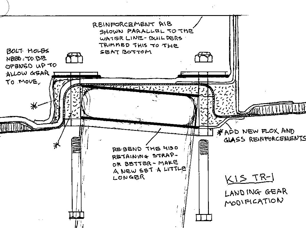
Main Gear - Moving the main gear forward to 70.5" I think OC has an excel file posted here on the forum somewhere of the various main gear changes that other builders made. Attached is a sketch of one builders gear mod.
Extension of the elevator by 3".
Landing gear, and elevator mods will make life easier in ground effect.
Tim - You have been flying the TR-1 a long time I am reasonably certain you have it figured out.
Robert - keep going - for inspiration think of Elden Lorah, 88, no chance for a medical but he continues to put the finsidhing touches on his 15 year old TR-1 project. We all need a reson to live
MT
| | - The Matronics KIS-List Email Forum - | | | Use the List Feature Navigator to browse the many List utilities available such as the Email Subscriptions page, Archive Search & Download, 7-Day Browse, Chat, FAQ, Photoshare, and much more:
http://www.matronics.com/Navigator?KIS-List |
|
| Description: |
|
| Filesize: |
140.17 KB |
| Viewed: |
16321 Time(s) |
|
|
|
| Back to top |
|
|
|
|
You cannot post new topics in this forum
You cannot reply to topics in this forum
You cannot edit your posts in this forum
You cannot delete your posts in this forum
You cannot vote in polls in this forum
You cannot attach files in this forum
You can download files in this forum
|
Powered by phpBB © 2001, 2005 phpBB Group
|

