 |
Matronics Email Lists
Web Forum Interface to the Matronics Email Lists
|
| View previous topic :: View next topic |
| Author |
Message |
messydeer
Joined: 13 Feb 2006
Posts: 214
Location: Bellingham, WA
|
 Posted: Fri Jul 16, 2010 8:20 pm Post subject: Electrical Noise Prevention Posted: Fri Jul 16, 2010 8:20 pm Post subject: Electrical Noise Prevention |
 |
|
Hi!
I'm finishing up my electrical wiring and am wondering about noise. I'm not sure what types there are, nor do I know all the sources. I have heard the alternator and the transmitting radio can cause problems. Also heard that anything with a pulsing signal could also be a source.
I have a 3 or 4 100-150 Mhz ferrite RF suppressors from MGL http://www.mglavionics.com/EMI_suppressor_for_VHF_frequencies.pdf. It sounds like MGL recommends putting them on any output from the radio, but not the antenna.
I've heard that twisting the feeder line to the noise maker with it's ground coming back from the device (or having the wires next to each other) will help cancel out EMF generated noise.
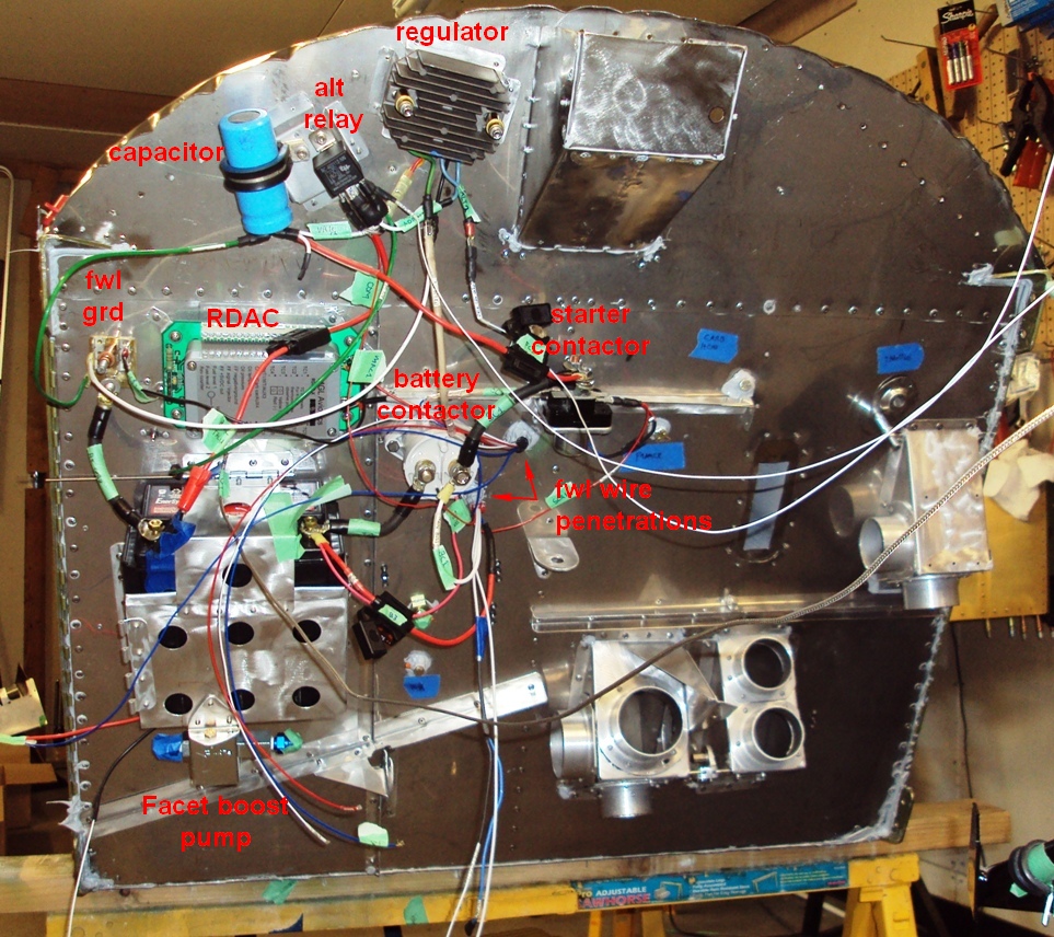
My schematic is posted in another thread: http://www.matronics.com/forums/viewtopic.php?t=72713. The two alternator leads are about 1' long and are wrapped together until one separates to go to the regulator and the other to the alt disconnect relay, which is right next to the regulator. The regulator output wire goes ~6" to a 10k micro (10 mili?) F 50V filter capacitor.
I forgot to label the left and right mag wires, which are dangling out the bottom center of the pic. The engine instruments will be 6 cht's, 6 egt's, fuel pressure sender, fuel flow sensor, OT, OP, carb temp, and tach. All these will plug into the RDAC above the battery. A shielded data cable goes from there back to the EFIS.
All the wires go through the firewall in either of two firewall penetations, then join together going to the right side, then back to the instrument panel and into a wire wrap along a light channel 'tray' along the bottom of the instrument panel. The pic shows the panel rotated 90 degrees in the open position.
Most of the wires hanging loose are grounds. They'll be bundled together in the final installation, and if needed, close to the panel feed wires already wrapped. Besides the mag wires (which are shielded), the only wire with pusling would be the boost pump. The radio (which may be a handheld) and strobe/nav/pos lights are not in. I know strobes are notorious noise makers. I have the shielded cable installed already in the wings.
How does this look to you? Thanks again for taking your time helping me 
| | - The Matronics AeroElectric-List Email Forum - | | | Use the List Feature Navigator to browse the many List utilities available such as the Email Subscriptions page, Archive Search & Download, 7-Day Browse, Chat, FAQ, Photoshare, and much more:
http://www.matronics.com/Navigator?AeroElectric-List |
|
| Description: |
|
| Filesize: |
243.3 KB |
| Viewed: |
8109 Time(s) |

|
| Description: |
|
| Filesize: |
422.35 KB |
| Viewed: |
8109 Time(s) |
|
_________________
Dan |
|
| Back to top |
|
 |
nuckolls.bob(at)aeroelect
Guest
|
| Posted: Sat Jul 17, 2010 2:11 pm Post subject: Electrical Noise Prevention |
|
|
At 11:20 PM 7/16/2010, you wrote:
| Quote: |
Hi!
I'm finishing up my electrical wiring and am wondering about noise.
I'm not sure what types there are, nor do I know all the sources. I
have heard the alternator and the transmitting radio can cause
problems. Also heard that anything with a pulsing signal could also
be a source.
<snip>
|
| Quote: | How does this look to you? Thanks again for taking your time helping me
|
Suppliers of product to the TC aircraft world
are encouraged if not commanded to worship
at that altars of the gods of blissful
system integration. Catechisms for these
orders are documented in RTCA DO-160,
Mil-Std-810, Mil-Std-704 just to name the
most prevalent.
By the time the system integrator is tasked
with finding a place to bolt it in and wire
it up to make it work, 99.99% of concerns
for unhappy experience are already addressed.
Even when the hardware has not been admitted
to the social A-List for the aviation community,
the risks for noise issues are relatively low.
A single point ground for all the instrument
panel mounted goodies and paying attention
to the manufacturer's installation instructions
goes a long way to crafting a noise free future.
Ferrite beads are found useful only when the
original designer of a potential noise
antagonist/victim didn't do their homework.
To assume that they would be useful before you've
identified a real noise issue is probably not
a good use of time . . . Fly the airplane
first . . . the ferrites can probably
be willed to the neighbor kid as slingshot
ammo.
Bob . . .
Bob . . .
| | - The Matronics AeroElectric-List Email Forum - | | | Use the List Feature Navigator to browse the many List utilities available such as the Email Subscriptions page, Archive Search & Download, 7-Day Browse, Chat, FAQ, Photoshare, and much more:
http://www.matronics.com/Navigator?AeroElectric-List |
|
|
|
| Back to top |
|
|
messydeer
Joined: 13 Feb 2006
Posts: 214
Location: Bellingham, WA
|
|
| Back to top |
|
|
nuckolls.bob(at)aeroelect
Guest
|
| Posted: Sun Jul 18, 2010 7:52 am Post subject: Electrical Noise Prevention |
|
|
At 11:20 PM 7/16/2010, you wrote:
<snip>
In this picture you show a "main bus" . . . what is this?
Normally, the main bus is a contiguous connection by means
of unbroken bar or strip to the power feed side of an array
of breakers or fuses. I.e., this component is already in existence
inside a fuse block . . . or is fabricated and configured
like the bus bars in this photo:
http://aeroelectric.com/Pictures/Breakers/Breaker_Panel_Busing_1.jpg
You also show a panel ground that appears to be on
the side of the fuselage. Is this a floating tie point
for the collection of all ground wires off the panel mounted
accessories? In the various z-figures, I suggest a gathering
of the grounds on what's called a "panel" or "avionics ground
bus". This is intended to offer a single point ground for a fist full
of wires and centrally located to the serviced accessories
(on the panel itself). Further, it is NOT grounded to the
panel structure . . . but serves as a handy way to extend
lots of grounds to the fire wall ground in fewer wires. For
a panel ground, you'd need something like:
http://aeroelectric.com/Pictures/Grounding/Avionics_Bus_3.jpg
and wired like:
http://www.aeroelectric.com/PPS/Adobe_Architecture_Pdfs/Z13-8Q.pdf
where I show 5 strands of 20AWG running from the panel ground
to the fire wall ground. This provides redundant, low resistance
connection (roughly 2 mOhms/Ft equal to 13AWG) between the
two busses. The 5 strands and panel ground provides a much
handier way to deal with grounds on the panel mounted
accessories.
Bob . . .
| | - The Matronics AeroElectric-List Email Forum - | | | Use the List Feature Navigator to browse the many List utilities available such as the Email Subscriptions page, Archive Search & Download, 7-Day Browse, Chat, FAQ, Photoshare, and much more:
http://www.matronics.com/Navigator?AeroElectric-List |
|
|
|
| Back to top |
|
|
messydeer
Joined: 13 Feb 2006
Posts: 214
Location: Bellingham, WA
|
| Posted: Sun Jul 18, 2010 10:41 am Post subject: Re: Electrical Noise Prevention |
|
|
| Quote: | | In this picture you show a "main bus" . . . what is this? |
This is a fuse block fed by a 10awg line from the battery contactor. I had incorrectly called it a 'bus'. Now I know better.
| Quote: | You also show a panel ground that appears to be on
the side of the fuselage. Is this a floating tie point
for the collection of all ground wires off the panel mounted
accessories? |
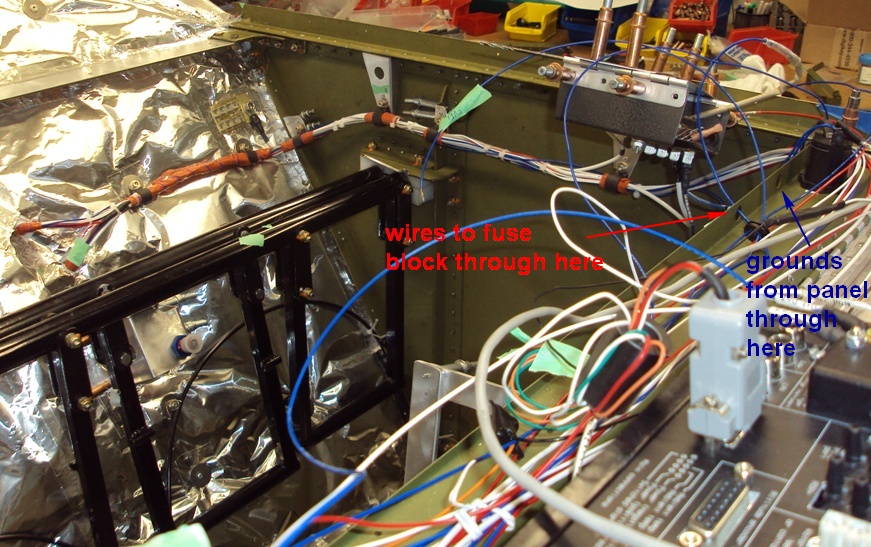
The panel ground is made of a section of 'forest of tabs'. I took one 48 tab forest and cut it into 3 pieces. One is on the hot side of the firewall and is connected to another section on the cool side via a 5/16" SS bolt. I forget the exact numbers, but when I measured the resistance of the SS, it was only slightly higher than brass. I chose SS because of its higher melting point.
A 10awg ground goes from the inside firewall ground to another section of tab forest for the panel ground. The panel ground is on the outside (lower side) of the cover to the main fuse block a few inches from the side of the fuselage. The cover will be piano hinged to the underside of the glareshield. In the pics, the glareshield is removed, so I've used a bent piece of metal to put the blocks in about the same position.
Next step is to wrap all the wires together in a spiral wrap starting from where teh bundle enters the tray on the right side of the fuselage. Feeders and grounds will branch off where shown.
| | - The Matronics AeroElectric-List Email Forum - | | | Use the List Feature Navigator to browse the many List utilities available such as the Email Subscriptions page, Archive Search & Download, 7-Day Browse, Chat, FAQ, Photoshare, and much more:
http://www.matronics.com/Navigator?AeroElectric-List |
|
| Description: |
|
| Filesize: |
255.2 KB |
| Viewed: |
8066 Time(s) |
|
_________________
Dan |
|
| Back to top |
|
|
tim2542(at)sbcglobal.net
Guest
|
| Posted: Sun Jul 18, 2010 5:29 pm Post subject: Electrical Noise Prevention |
|
|
Hi Bob and thanks for the help.

I am trying to understand your comment re: grounds below. Why is the 5X20

AWG better than a single large wire? And why separate panel and avionics

grounds? In my case I had planned either a DB 25 or forest of tabs approach

on the front of the (glass) panel with all local ground needs tied in there,

then a suitable ground run back to the battery. With a rear mounted battery

do you then recommend the 5X20AWG run all the way to the back?

For reference I am building an all electric COZY.

Thanks, Tim Andres


   I suggest a gathering

   of the grounds on what's called a "panel" or "avionics ground

   bus". This is intended to offer a single point ground for a fist full

   of wires and centrally located to the serviced accessories

   (on the panel itself). Further, it is NOT grounded to the

   panel structure . . . but serves as a handy way to extend

   lots of grounds to the fire wall ground in fewer wires. For

   a panel ground, you'd need something like:


http://aeroelectric.com/Pictures/Grounding/Avionics_Bus_3.jpg


   and wired like:


http://www.aeroelectric.com/PPS/Adobe_Architecture_Pdfs/Z13-8Q.pdf


   where I show 5 strands of 20AWG running from the panel ground

   to the fire wall ground. This provides redundant, low resistance

   connection (roughly 2 mOhms/Ft equal to 13AWG) between the

   two busses. The 5 strands and panel ground provides a much

   handier way to deal with grounds on the panel mounted

   accessories.

   Bob . . .
| | - The Matronics AeroElectric-List Email Forum - | | | Use the List Feature Navigator to browse the many List utilities available such as the Email Subscriptions page, Archive Search & Download, 7-Day Browse, Chat, FAQ, Photoshare, and much more:
http://www.matronics.com/Navigator?AeroElectric-List |
|
|
|
| Back to top |
|
|
messydeer
Joined: 13 Feb 2006
Posts: 214
Location: Bellingham, WA
|
| Posted: Mon Jul 19, 2010 5:45 am Post subject: Re: Electrical Noise Prevention |
|
|
| Quote: | 5 strands of 20AWG running from the panel ground
to the fire wall ground. |
Good question, Tim.
I had missed that point. I have a single 10awg wire going from my panel ground to the firewall, not 5 smaller ones. I used 10awg for my main feeder, so chose the same size for the ground.
| | - The Matronics AeroElectric-List Email Forum - | | | Use the List Feature Navigator to browse the many List utilities available such as the Email Subscriptions page, Archive Search & Download, 7-Day Browse, Chat, FAQ, Photoshare, and much more:
http://www.matronics.com/Navigator?AeroElectric-List |
|
_________________
Dan |
|
| Back to top |
|
|
nuckolls.bob(at)aeroelect
Guest
|
| Posted: Mon Jul 19, 2010 11:48 am Post subject: Electrical Noise Prevention |
|
|
At 08:25 PM 7/18/2010, you wrote:
| Quote: |
Hi Bob and thanks for the help.
I am trying to understand your comment re: grounds below. Why is the 5X20
AWG better than a single large wire?
|
Single wire is single point of failure . . . although
it can also be argued that 5 parallel paths offers the
POTENTIAL for an undetected, latent failure. Further,
at higher frequencies, multiple parallel strands are
lower impedance connection than a single strand (or
one thin, wide strap would be good too). The most
compelling reason was to offer a high probability
for installation success . . . the D-sub connector
accepts 20AWG wires. Going with a single, larger
conductor leaves it up to the installer to fabricate
the joint between the ground wire and the avionics
ground bus.
The short answer is "no single reason . . . but
several significant reasons". But those reasons
are rooted in the features of a D-sub based
ground bus. Other configurations change the
selection of ingredients that go into YOUR
recipe for success.
| Quote: | And why separate panel and avionics grounds?
|
Sorry about the vague vernacular. For the purposes
of this discussion, let's use Figure Z15, View B
and move the battery from the nose back to the
rear spar and ground it to the firewall ground
stud. An avionics ground is on the panel sheet
and intended to bring small power/signal wires
to a common ground. The "panel" ground is captive
to the airplane and would take care of grounding
airframe accessories not generally associated with
music, bells, lights and pointers.
| Quote: | In my case I had planned either a DB 25 or forest of tabs approach
on the front of the (glass) panel with all local ground needs tied in there,
then a suitable ground run back to the battery. With a rear mounted battery
do you then recommend the 5X20AWG run all the way to the back?
|
The 5x20 configuration presumes a tractor airplane with a forest-of-tabs
on one or both sides of firewall.
| Quote: | For reference I am building an all electric COZY.
|
Okay, where are your panel equipment power distribution
busses located? How about doing a sketch on where the
power and ground busses are located along with a list
of loads on each bus.
Bob . . .
| | - The Matronics AeroElectric-List Email Forum - | | | Use the List Feature Navigator to browse the many List utilities available such as the Email Subscriptions page, Archive Search & Download, 7-Day Browse, Chat, FAQ, Photoshare, and much more:
http://www.matronics.com/Navigator?AeroElectric-List |
|
|
|
| Back to top |
|
|
nuckolls.bob(at)aeroelect
Guest
|
| Posted: Mon Jul 19, 2010 11:48 am Post subject: Electrical Noise Prevention |
|
|
At 08:45 AM 7/19/2010, you wrote:
| Quote: |
> 5 strands of 20AWG running from the panel ground
> to the fire wall ground.
Good question, Tim.
I had missed that point. I have a single 10awg wire going from my
panel ground to the firewall, not 5 smaller ones. I used 10awg for
my main feeder, so chose the same size for the ground.
|
Since you're not using a d-sub avionics ground, leave
the 10AWG in place.
Bob . . .
| | - The Matronics AeroElectric-List Email Forum - | | | Use the List Feature Navigator to browse the many List utilities available such as the Email Subscriptions page, Archive Search & Download, 7-Day Browse, Chat, FAQ, Photoshare, and much more:
http://www.matronics.com/Navigator?AeroElectric-List |
|
|
|
| Back to top |
|
|
tim2542(at)sbcglobal.net
Guest
|
| Posted: Mon Jul 19, 2010 1:55 pm Post subject: Electrical Noise Prevention |
|
|
Thanks Bob! That makes sense especially when using the D sub.
In my case the fuse blocks will probably be under the Right seat, about a
30" run up to the avionics and various switches. I'm looking into using a
swing down panel to hold the fuse blocks under the panel, but it looks
complicated. There will be 5 breakers in the panel as well. The ground bus
will be in front of the panel in an undetermined location but close to the
avionics stack.
I'm still working on the drawing and will post it soon.
| Quote: | For reference I am building an all electric COZY.
|
Okay, where are your panel equipment power distribution
busses located? How about doing a sketch on where the
power and ground busses are located along with a list
of loads on each bus.
Bob . . .
| | - The Matronics AeroElectric-List Email Forum - | | | Use the List Feature Navigator to browse the many List utilities available such as the Email Subscriptions page, Archive Search & Download, 7-Day Browse, Chat, FAQ, Photoshare, and much more:
http://www.matronics.com/Navigator?AeroElectric-List |
|
|
|
| Back to top |
|
|
messydeer
Joined: 13 Feb 2006
Posts: 214
Location: Bellingham, WA
|
| Posted: Tue Jul 20, 2010 7:05 pm Post subject: Re: Electrical Noise Prevention |
|
|
| Quote: | Since you're not using a d-sub avionics ground, leave
the 10AWG in place.
|
Goodie!
Another person told me they'd expect noise if the P-leads are in the same bundle to the panel. That's how I've got them. But I don't have any audio system hooked up yet. Those wires would cross the P-leads or at a right angle.
| | - The Matronics AeroElectric-List Email Forum - | | | Use the List Feature Navigator to browse the many List utilities available such as the Email Subscriptions page, Archive Search & Download, 7-Day Browse, Chat, FAQ, Photoshare, and much more:
http://www.matronics.com/Navigator?AeroElectric-List |
|
_________________
Dan |
|
| Back to top |
|
|
|
|
You cannot post new topics in this forum
You cannot reply to topics in this forum
You cannot edit your posts in this forum
You cannot delete your posts in this forum
You cannot vote in polls in this forum
You cannot attach files in this forum
You can download files in this forum
|
Powered by phpBB © 2001, 2005 phpBB Group
|

