I drilled #41 through the longeron, then used that as a guide to drill #41 through the weldment. Finally I backdrilled #30 through the weldment and longeron. To do that, I needed to remove the firewall from the jig. Actually, I think that this step could be done before setting up the jig. Note the different rivet patterns on the top and side of the longerons -- rivet spacing is 3/4" on the side of the longeron, 1/2" on the top.
My F695 gussets (found in the plastic parts bag) don't fit well at all. I'll need to add some shims (maybe .063 or so) at the firewall end. The problem is that the horizontal firewall brace is slightly above the weldment.
FJ says to drill some #40 holes to temporarily hold the skeleton together. These are needed so that the skeleton is held in place whilst the skins are fitted. Later, rivets through the skin will hold the skeleton together securely. When I was doing this section, I couldn't see why the -3 rivets were needed, nor where to put them where they wouldn't violate edge-distance on the #30 holes, so I didn't put any in. I don't think that will cause any problems. I can still use the following technique, or, worst case, temporarily fit -4 rivets in a few holes and drill them out once the skins have been fitted to all the other holes.
RV-list message posted by gil@rassp.hac.com (Gil Alexander): Easiest practise (and the RV6 video does this, but it is not explicitly mentioned) is to use a -3 rivet at all stringer/bulkhead, and longeron/bulkhead locations, assemble the fuse. frame, and then plan the final skin rivets to straddle these locations. Vans instructions have a brief mention of this, and also say you can offset the first rivet as much as possible at these intersections during frame riveting, and then put a bulkhead/longeron/skin rivet in the center of these intersections. This sounds dificult to do with the limited area available, and still meet edge distances etc.
Pre-drill the skin-attach holes in the ribs, longerons, etc, then back-drill through the skin. You'll probably want a right-angle or 45-degree drill to get round the flanges.
Note that the plans call for universal, not flush, rivets on the top of the longeron/firewall attachment.
Note that the F604 bulkhead sits underneath (on top of) the longeron... it's only attached to the longeron by the F604F parts.
You should notch the F604F on the outboard side to allow room for the static line and/or tail/antenna wiring.
My F604 bulkhead was exactly the right height -- no trimming needed.
A key technique to setting up the bulkheads correctly is to mark the correct distance between the bulkhead being installed (the F604) and the previous bulkhead (the F601) on two or three pieces of angle. Now clamp the pieces of angle to the bottom (top) of the bulkheads so that the marks align with the bulkhead webs. I used this technique when installing all my bulkheads.
Note that the 1 1/4" side is the vertical side of the longeron.![]()
When mounting the F655 gussets, I found that the 3/32" countersunk holes already in the F604 were in the wrong place, making it difficult to place the 4 required rivets between the F604 and the F655. I drilled out the 3/32" hole to #30 and use it to attach the F655 to the F604.
My diagonal longerons were 27 7/8" long. The front end needs about 4" of the angle trimmed off to fit the weldment. This is shown in the video.
The middle longerons were 28 5/16" long. Firewall-to-skin distance is 5/8", so need to trim the small angle and longeron. When making these parts, make the aft end (with the double bend) first. Debur the aft end before bending... after bending, you may not be able to get between the bent parts. At the front, drill as close to the longeron flange as possible to avoid edge distance problems.
The notch in the F602s is 1 1/8" long.![]()
The floor stiffeners will attach to the false spar by some little brackets made from scrap 1/16" angle. Eventually they will attach to the spar itself (I guess).
RV-List message posted by: "Stephen J. Soule"<SSoule@pfclaw.com>: The aft end of the inboard stiffeners bolt via brackets that you make to the fuel selector console and wing spar. It is shown, but not very well on the drawing that depicts the fuel selector console.
When fitting them, use something (I used my F606C angle) to simulate the skin line. Note the spacers at the forward end of the outer stiffeners (Dwg 31 Section F-F'). To get a neat fit, curve the edge of the spacer to match the inside curve of the 1/16" angle. Also see Vans manual page 8-8 in the section on the F672.
I didn't make the floor stiffeners yet -- I'm waiting to see exactly how they fit.
I found when I fitted my rudder pedals that my cables rub against the bottom of the bushings in the F602, and 'click' when the end of the terminal goes through there. I guess that that hole should have been drilled a little lower in the bulkhead.
I've left mounting the pedals until later, so that I can get them the right distance for my leg length. Details of this section will be in the next section of the Guide.
Similarly, I trimmed 1/8" off the slight angle on the long side of the F657 gussets.
RV-List message posted by: "Randall Henderson"<randallh@home.com>: I made the F615 match the curve of the arm rest. I did have to add a shim under one end of the rib since this shortened the rib just a smidge and you need to adjust for the distance between the spars. I think some people just leave this rib straight too but it seemed to me better to make the skin not want to go from curved at the middle to straight at the bottom.
My F604-F605 distance is 25 15/16".![]()
The F618s were the only ribs that needed moving to clear bolt heads... the web lines up exactly with one of the 3/16" bolts. I moved the ribs slightly, so that the bolt goes through the flange of the F618. Therefore, I left out the 2nd-to-top (2nd-to-bottom) rivet.
Note that the distance apart of the centre ribs is critical -- outside flange to outside flange needs to be 4" (or less). The best way to check that is to clamp the F-641 part in place. This will eventually be screwed to the rib flanges via platenuts.
Before attaching the F618/F619 ribs permanently, check clearance of the control column against the ribs. I fitted my c/c mounts as per the plans, and had to trim the top of the rib holes to allow full movement. Lowering the c/c mounts would have fixed (or at least minimised) this problem.
RV-List message posted by: Dennis Persyk<dpersyk@worldnet.att.net>:
Frank Justice suggests both ribs be made removable as it makes control
assembly servicing easier -- I agree. I used AN3s with nut plates at the
splices as they are easier to tighten/loosen in the narrow confines of
the rib cavity than Phillips head screws.
The notches are for the close tolerance bolt nuts which need more clearance than just a notch. I was just fitting mine with he wings installed and I had to cut them all the way through. The flange is supported by several 8-32 screws so cutting a gap out of the rib seems to do little harm strength wise.
The location of the screws attaching the removable W619 sections to the F604 bulkhead is awkward... the second screw lines up exactly with the control column when it is fitted, so that the control column assembly needs to be removed to remove the W619s. :-( I think the best approach would be to fit nutplates on the W619s (rather than the front of the F604), and drill corresponding holes in the spar centre section. But check with Vans first before drilling holes in the spar!
RV-List message posted by: "Japundza, Bob"<Bob.Japundza@EnterpriseWise.com>:
I have the 4-point Hooker belts in my -6. Here are my observations
with them:
On the -6, the seat belt attach points are a bit inside of the seat back, not perpendicular to the edge of the seat back. Because of this, the seat belts have to bend outward somewhat to get around the seat back, and on my plane, one of the formed rib edges of the seat back rubs on the seat belt and over time I suspect it will wear into the belt. If I had to do it over again, I would locate the attach points further out so they don't have to bend around the seat back.
The Hooker belts take AN-4 bolts for the attachment to the brackets. If I remember correctly, the plans show 3/16" holes. Also, the Hooker belts have a bushing which the AN-4 bolts go through; it's not just a hole in the bracket like the other belts I've seen. The brackets will therefore have to be spaced wider than the 1/8" or so the plans call out. I think I have them spaced 1/4 inch; I'd have to check...its been a while.
A friend of mine has the same belts in his -6 and he has mixed feelings about them. His only beef is the shoulder pads are pretty wide and tend to rub against your neck.
From Jim Cones' newsletter Jan 97: Alex Peterson has come up with a solution to the right seat inboard seatbelt anchor interference problem. He cut off the flange on the offending seat rib and installed a piece of angle facing the other way. The anchor sandwiches between this new flange and the F605 and eliminates the need to trim the anchor. When I had this problem, Tom said to just trim the anchor and make it fit. This weakens the anchor a bit and Alex's solution appears better.
In one of his RVAtor articles, Van described the problem of 'submarining' and suggested that a 5-point harness would be a good idea. It also seemed like a good idea to me. Dennis Persyk, John Warren, and others provided the RV-list with information about how strong harnesses and their attach points need to be. Go to Matronics Search Engine and search for "Seat Belt and Shoulder Harness Design".
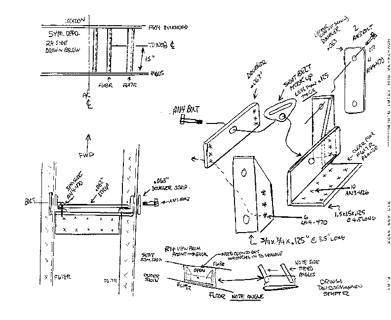
Later, Dave McManmon (McManD@aol.com) sent me a drawing of how to make the necessary attachment point for a crotch strap. I didn't start building it until I'd already drilled the F677 skin to the skeleton -- that was a mistake. It's much easier to build in the attach point before drilling the skins to the skeleton. It would be even easier to build before rivetting the seat ribs to the bulkheads -- rivet the attach point between ribs F617 and F618 before rivetting them to the skeleton.
My notes on this drawing (some of these points are also included in the drawing). For brevity, I'll call the parts as follows:
A1 -- the large piece of angle (1 1/2" x 1 1/2" x 1/8" x 4 1/2")
A2L and A2R -- the two smaller angles (3/4" x 3/4" x 1/8" x 3 1/2")
A3 -- the large doubler plate ( 1 1/2" x 4 1/2" x .063")
A4 -- the small doubler plates (3/4" x 3 1/2" x .063")
The 2 LH drawings are plan views at different scales.
The small diagram at the bottom referring to the 'tipped angle' is a view from front to back of the RH side. Because the outside skin isn't horizontal between the F617 and F618 seat ribs, a vertical member won't be perpendicular to the skin. That's why the LH half of the bottom drawing is shown at an angle -- not because it was roughly drawn. The RH half of the drawing shows the same thing, but with A1 shown horizontal, and the vertical parts therefore 'tipped'. I think perhaps he's exaggerated the slope, but maybe not. Note that because of this slope, the ends of A1 shouldn't be square... they should about 1/4" to one side. Similarly A3 isn't rectangular -- start with a piece 4 1/2" long and taper the sides back 1/4" from vertical.
I made the A2 pieces from 1" x 1" x 1/8" angle -- that gave me a little leeway if things didn't fit too well. I think I'd do that again. They only needed to be 3 5/16" long. In fact, the one which must fit between the rib flanges can't be any longer. Note that they're tapered from above the A1 to the top. I also tapered the other sides back about 5/8", to clear the rivets that attach the skin to the rib.
The A4 doublers need to be smaller than shown in the diagram -- mine
are 2 7/8" long. They need to fit between the flanges of the F618 rib.
![]()
![]()
![]()
![]()
The large drawing at the top right is an exploded view of the fitting.
It doesn't include the .063" doubler on the LH side. The flange of the
angle on the LH side should be visualised as going away from the viewer.
I attached the A1 to the skin with 1/8" rivets rather than 3/32" as specified. That's mainly because I don't have any long AN426-3- rivets. I need extra long rivets because I used some al pieces I could get locally rather than ordering parts from Vans, so I ended up making my A1 pieces from 3/16" angle instead of 1/8". Similarly, I used 1" x 1" instead of 3/4" x 3/4" for the A2 pieces. It is important that these pieces are 1/8" thick, since they leave a 1/8" gap between the A1 and A3 pieces for the seatbelt buckle to fit into.
I'll use AN3 bolts to attach the A2 pieces to the ribs. That's mainly because it'll be really difficult (impossible) to get in and rivet in there now that the ribs are rivetted to the skeleton.
The 1/4" bolt hole through the A1 and A3 parts to attach the seat belt to to the attach point don't go in the middle of the piece (the control columns are not centred between the F617 and F618 ribs). I drilled the bolt holes 1 1/2" from one side and 3" from the other.
Mel Jordan wrote: I too have just made my attach points today.
As I had already made and drilled my seat pans, I made two strips of .025
X approx. 18in, drilled them to match the seat pan and clecoed them to
the ribs to hold everything in alignment when I made my attach points.
I would consider this critical if you have already drilled the seat pan.
I also moved my attach points one inch further forward than the plan showed
(16" from 605). I sat in a friend's 6 and think that the crotch strap
should come out of the control stick opening so that it holds the seatbelt
slightly forward and down. I am going to put a split in a piece of 1/4
inch soft alum tubing and place this on the edge of the opening so that
it won't cut the strap material.![]()
![]()
![]()
![]() In
the third picture,you can see the alum. straps that I made to hold the
ribs in alignment while I drilled the mount to the airframe. If I
had not done this, then the floor pans would no longer have matched the
rib holes.
In
the third picture,you can see the alum. straps that I made to hold the
ribs in alignment while I drilled the mount to the airframe. If I
had not done this, then the floor pans would no longer have matched the
rib holes.
For safety the installation must be done after the complete movement of the controls and aileron trim have been established. This way you can clear and trim any part of the installation as required. I temporarily installed my control columns to see how close it got to my proposed crotch strap attachments. My 5th points don't interfere with the control column. That's mainly because I installed them several inches too far aft. I expect that they'll still work OK though. However, it's clear to me now that the attachment should be no further aft than the bend in the seat floor.
Note that the distance apart of the centre ribs is critical -- outside flange to outside flange needs to be 4" (or less). The best way to check that is to clamp the F-640???? part in place. This will eventually be screwed to the rib flanges via platenuts.
I needed to trim my F627 and F626 flanges to clear the F605 flange.
I attached the F627R, F606, F629, F630 using the same rivets. However, the F630 is only 3" wide, and F627L and F627R are 4" apart. The F629 is attached to the F630, F627L is attached to the F606 only.
As per FJ's note about a mistake in the kit, I had to shorten the F627 and F626 ribs by about 3/16". I didn't need to shorten the F625, which fits at an angle.
I had to move the F626s to 9 1/4" from the centreline to align with the holes in the F605 stiffener.
The 'large hole' which F627L needs to be notched round is the trim cable hole.
My F625 web aligns with the middle of the first 'tab' as the F606 starts to curve. That 'tab' is needed to attach the F623 side rib. It would have been better if I had moved the F625 inboard a little (to 13" from the centreline) so that it is clear of the F623.
The .032 x 3/4" x 2" strip to butt attach the F623 to the F606 is impossible.
Inside the F623 at the end, it is only 1/4" wide! I trimmed back the flanges
of the F623 about 1/2" or so, so that a reasonably wide strip could be
used. Even then, the strip was a pretty odd shape as it clears the F623
flanges and F625 web.![]()
There was a post on the List about a mistake in the 6A step instructions and they are 100% right! Instructions say to run tube flush with web of that wierd-looking outside rib. No! Centre your hole so the edge of the tube is 1/4 to 3/8 above (below in the jig) the rib web.
After much thought I split the bulkhead from longhorn to longhorn about one inch from the flange. I then fashioned a splice plate from .032 material for it after moving the flange into proper position. My bottom skin is now going to fit very, very well. See Sam Buchanan's page -- he had the same problem and solved it the same way.
I didn't have this problem... well not quite. I found that my F610 and F611 were too tall by about 1/8". When I trimmed them down to the right size, everything lined up nicely.
To fit the side J-stringers, you'll need to trim the 'flange' off at the aft end (about 1 1/4" for the two flanges on the F612).
To fit the bottom (top) J-stringers, you'll need to trim the 'flange' off at the ends (about 5/8" at the aft end for the flange on the F610, about 5/8" at the forward end). You'll also need to make the notches in the bulkheads L-shaped.![]()
I didn't have the Kit Problem mentioned by FJ... my fuselage was bought in late 1998.
The position of the F611 bulkhead depends on the length of the Wd609 tailspring mount. Therefore I changed the assembly order a little, mounting the Wd609 before fitting the F611... that seemed more sensible than measuring and hoping. Note: Read through Vans notes. It is important to NOT drill the Wd609 to the F612 bulkhead at this point! (I hope it's not too important, since that's exactly what I did.) Don't permanently attach the Wd609 yet... it'll have to come out later to allow you to drill the skins to the F611 and F612.
I used my angle grinder to notch the longerons... it produced a notch just the right width to clear the F611 bars. Note that the bars angle outward, so you will need to spread the longerons a little to slip the F611 in place. Since the longerons aren't parallel at this point, the notches won't be at right angles to the longerons.
Attach the upper (lower) side stringer to the F622 and F606 bulkhead before drilling it to the other bulkheads. Otherwise, the F606, F607, and F608 may bend forward/aft a little. That leads to the following scenario: The F622 is firmly attached to the F605. The F611 and F612 are firmly attached. If the stringer is clecoed to the F611, it won't reach the F622 by 1/8". If clecoed to the F622, it won't reach the F611. :-(
When fitting the J-stringers, the lower (upper) side stringer only needs the 'curl' trimmed clear; there's already a notch in the F611 for it. The other stringer needs the entire 'flange' trimmed off to clear the flanges of the F611.
The F611 reinforcement angle needs to be about 6 1/2" long. The ends aren't square -- they angle out about 1/8" to follow the contour of the longerons.
The F610 reinforcement angle is 10 7/8" long, tapering down to 10 1/2" at the F610 bulkhead.
On the fuselage the F610 bulkhead is the general area where the horizontal stabiliser mounts and there is a hefty 1x1 piece of angle that is fabricated to tie this bulkhead and the longerons to the horizontal. Well, Justice says to "Drill the rivet holes in this angle," prior to fitting. All well and good, but he should add a cautionary note, "Do NOT drill the 3/16 bolt holes in same."
The way I read FJ's notes, it says to drill the holes to attach the angle to the bulkhead, not the holes that will eventually attach the HS to the fuselage.
If you're building a 6A, you might want to look at Cecil Hatfield's No-catch Tailhook.
You may not have much choice in whether the rivets that attach the stringers to the bulkheads also attach the skins. I'd decided not to do this -- I wanted the skin rivets to straddle these rivets. However, with a rivet spacing of 1 1/4", these rivets should be at most 5/8" from the centre one. In many cases, the joggle or the slot in the bulkhead extends to 5/8" from that centreline.
Only rivet every second rivet attaching the forward upper corner weldments to the longerons. The intermediate ones will later be rivetted through the forward skin.
A couple of the rivets holding seat ribs to the F604 are difficult to
buck. I backrivetted those, using an ordinary bucking bar as the 'plate'.
That worked fine.![]()
If you're building a taildragger, don't rivet the stringers or longerons to the F611 or F612 bulkheads too early. You'll need to remove the tailspring mount to get in and drill the skins to the bulkheads and stringers. To maintain alignment whilst drilling the F679, I dimpled the bulkheads and stringers, then taped flush rivets in the holes. Pretty much the same goes for the F610.
Don't rivet the angle across the front of the F611 just yet -- it'll interfere with setting the skin rivets.
Before bolting the Wd609 in place and rivetting the skins around it, don't forget to drill the 1/4" hole through it and the tailspring. And when drilling this hole, make sure the tailspring axle is vertical.
RV-List message posted by: WPAerial@aol.com: I found putting telephone books under cargo straps work really well when cinching up wing or fuselage skins. The books take the form of the skin.
Don't forget to drill the 1" hole just aft of the F611.
When FJ says longerons, he means stringers.
Trim the front edge flush with the front of the F606. Be careful trimming the aft corners... you don't want to leave a hole between the F673, F678, and F679!
Later, I figured out I had pulled the side skins down too tightly -- that pushed the bulkheads forward at the curved section.
Lots of diving under the jig to drill pilot holes, followed by climbing out again to drill all the holes in between. George O's suggestion to use a mechanic's creeper is excellent.
I located the 3" spaced holes in the longeron at 3/4" aft of each bulkhead, then at 3" spacing after that. The idea is to put the final 1" spaced holes about 1/4" aft of the bulkhead and 3/4" in front, thus leaving good distance between them and the 3" holes, and between them and the bulkhead/longeron attach rivets.
George O and Sam Buchanan didn't trim these skins to the F610/side stringer as shown in the plans. George justifies leaving it there for aesthetic reasons (no seam on the side of the fuselage) and to add strength. I did, figuring that (a) there's a fair amount of weight to be saved in all that metal, and it's a long way aft, and (b) the seam is under the HS where it'll be out of sight. If you do trim it, again be careful trimming the corners where they meet the aft edge of the F678.
There's not a lot of leeway when drilling these to the curved part of the F606. I put two holes in each tab... there's just enough edge distance (3/16") and between-rivet distance (9/32") to fit. There's no other way to get the 3/4" spacing called out in the plans.
Actually, I don't think it's a good idea to drill these yet (although
that's what I did). Following FJ, the skins will have notches cut to match
the notches in the F606. ![]() They will then be bent out to match the curve of the 'cone' in the aft
of the F670 side skins. I'm concerned that the holes in the F606 and F673
won't match up after the bend.
They will then be bent out to match the curve of the 'cone' in the aft
of the F670 side skins. I'm concerned that the holes in the F606 and F673
won't match up after the bend.
Some people have chosen to cut these panels with a fly cutter, so obviously
they lose a little of the fore-aft length. I went for rectangular, because
(a) I have large hands, and there's been comment on the RV-list about how
difficult it is to get into this space, and (b) I wanted to use the cut-out
as the panel. I cut the holes using my jigsaw... that took about 1/16"
of metal out. If it looks too bad, I'll cut some new access panels from
scrap.![]()
Note that 18 Years of the RVAtor shows how to make extra large access panels.
I made my slot 1 1/8" long and 3/8" across, and elliptical (my recollection of high school maths and conic sections tells me this is right) in shape. Then I tried to fit the rudder cable end through it... oops... the slots are now more teardrop shape, with the wider end to the rear. However, as Tom Barnes <skytop@megsinet.net> said in an RV-list message: The cable fairing completely hides the hole, so depending on the length of your fairing, the hole can be longer or shorter. I did test out removing the cables with the fairing in place -- I figure out that, in 20 years time when the cables wear out, I'll be able to drill out the rivets along one side of the fairing and be able to swap cables, then reattach those three rivets. Therefore I didn't use nutplates as suggested by FJ.
I bought the Avery fairings. They were a disappointment -- I was expecting
some parts that were ready to rivet on. Instead, I had to trim and shape
them.![]() I'd recommend making the fairings for free as
described by Sam Buchanan.
I'd recommend making the fairings for free as
described by Sam Buchanan.
RV-List message posted by: "Dennis Persyk"<dpersyk@worldnet.att.net>: Mine are 1 1/8 long. I drilled two holes 3/8 dia with 1 1/8 edge-to-edge and cut out in-between on connecting tangent lines. I also fashioned two right-angle tabs riveted to the aft side of F611 to hold Adel clamps at the optimum angle to captivate the rudder cable tubing guides.
![]()
I attached the F677 skin first. I pilot-drilled the skin at each side
to the F605, then drilled the in-between rivets as per the aft skin. I
then backdrilled all the rest of the holes using a 12" bit, working outwards
from the first line. I clecoed every hole as it was drilled.![]()
![]()
The aft outside, from about 2" aft of the rear spar attachment, of these skins is trimmed to take them in to the edge of the fuselage -- mine corresponded very closely with the shape shown in the plans.
When drilling the aft splice line, be aware where the F628 will attach, and avoid putting a rivet there.
Note that later there will be some holes cut in the corners for the flap linkage.
FJ says to use -4 rivets instead of -3 for some of the rivets through the F604. Since 5/96, the plans say to make them all -4 rivets.
Be careful where you place the holes (nominally 1 1/4" apart) to avoid rib webs and the control column mounts.
When drilling the F672 to the lower (upper) firewall stiffener, be aware of attachments above (below) the stiffener, especially the F601J angles and the weldments. Locate holes in line with the F601Js as near to the edge of the stiffener as possible to avoid interfering with the F601J. Similarly, the holes which line up with the weldments can be moved a little out from the centre of the stiffener. Don't pilot drill the outermost holes attaching the F672 to the firewall. You can't backdrill them because the weldment is in the way.
It might be a good idea to countersink the holes attaching the stiffeners to the firewall, flush side inboard.. The battery box needs to go between the stiffeners, and it's flanges otherwise will interfere with the rivet heads.
The cowl hinge pin mentioned by FJ is shwn in Dwg #31, section E-E'. I didn't do anything about this, mainly because I wasn't sure how much shimming I would need to do. I'm getting the newer epoxy cowl mentioned in the Dwg, but the dwg mentions .032" (I think) skin thickness rather than the .040" of the F672. Maybe it's showing the side skins?
If (like me) you're building a taildragger, trim back about an inch or two of the ends of the forward edge of the skin by about 3/16" wide. This should match the firewall bottom flange, and is to allow clearance for the gear legs.
I'm not sure what FJ means when he says "Mark the edge of the bottom skin extension on it [the side skin] and trim out the material about 1/8" more than the mark indicates". I guess it means cut 1/8" inside the mark, so that the skin is 1/8" undersize. Mentioning the 'extension' suggests to me that he's talking about the F676/F677 bottom skins. However, I'm not about to trim a skin undersize based on guesswork... I'll figure this out some more later.
I cut out the main spar and aileron pushrod openings early on, rather than later as indicated by
FJ. That was mainly because I'd made my false spar so that it extends
out the side of the fuselage to eventually be used as a support when the
fuselage comes out of the jig. My wiring conduit is in the leading edge
of the wing so I will need to drill holes forward of the spar hole in the
side skin for that.![]()
I assumed that the tank skin would butt up hard against the outside of the fuselage, and I thought I'd save myself some time and drilled the fuel and fuel vent holes in the side skins. Bad move! There's a gap of 2-3" between the fuselage and tank, so (in particular) the vent lines don't come in where the vents come out of the tank.
I pilot-drilled all the holes in the skeleton 3/32", then backdrilled
#41 from inside the fuselage. Don't pilot-drill the flanges of the F623,
nor along the bottom (top) of the F615 -- they're impossible (or at least
very
difficult) to backdrill, even with a close-quarters drill set.![]()
Be very aware of the different rivet-spacings, and different sizes. Mostly (although not all) they're -4 rivets forward of the F604. The rivets in the F615 are all -4. The rest are all -3.
When drilling the curved 'cone' section at the aft end of the F670 to
the skeleton, it is really important to drill and cleco it
to the F606 first, *then* to the bottom skin/F623. I did one in the opposite
order and then spent hours fixing an unsightly gap between the F670 and
the aft skin.![]()
Again, I drilled the F670 to the al angle on the sides of the firewall, but won't rivet it together yet (this is suggested by Vans in the manual). I guess there's hinges to go here, as for the F672. I drilled the holes in the angle first, then backdrilled through the skin. Of course, the vertical 6x2 which supports the firewall is in the way. After rivetting the F670 to the skeleton up to the F604, I cut the 6x2 off using my Skilsaw -- it won't be long before the fuselage comes out the jig.
If you use the NACA ducts on the forward fuse for cabin air, DON'T permanently install these babies until after your final (yep, final.. painted, everything) installation of the rudder/brake pedals. With the vents permanently mounted in the "correct" location, getting the pedals in or out is almost impossible. If you move the vents up a couple of inches, it might be easier.
Van's also recommends not installing the vents until after the pedals
have been installed. However, that would mean cutting the holes and fitting
after the skin was rivetted to the skeleton. So I took a deep breath and
cut the holes earlier. I drew the position of the longerons, etc, and the
probable position of the rudder pedal mount block on the inside of the
skin. I cut out the paper template supplied by Vans and used that. It would
probably have been better to glue it to cardboard, but with a little fiddling
about, it worked out OK. I chose a position for the front edge of the hole
centred 3 1/2" down from the edge of the skin, and 3" aft of the front
skin edge. I then clecoed the skin to the skeleton and used a level to
draw a horizontal centre-line for the hole, placed the template, drew,
and cut out the hole.![]()
Some RV-listers recommend just using ProSeal to attach the vents to the skin.
RV-List message posted by: "Paul Besing" <rv8er@home.com>: Here is a picture of my installation. I used RTV and two rivets. One on the leading edge, and one on the trailing edge. Be sure to make a doubler plate or small washer on the backside, or the rivet will just dig into the plastic.
RV-List message posted by: Alex Peterson <alexpeterson@cwix.com>: I used about six -3 flush rivets and small aluminum AN washers on the inside. I also used RTV sealer between. The rivets were just barely set, and the holes in the plastic are oversized.
I did this, but used 1097 'cheater' flush rivets -- the heads are smaller than 426 rivets, so the skin can be countersunk (a few turns of the deburring tool is sufficient). I think putting a rivet aft of the vent would be difficult -- the outlet flange would get in the way. I put 3 rivets in the top flange of the plastic vent and 3 in the bottom, spread about 3" apart.
If you're building a tip-up canopy (and maybe if you're building a slider... I haven't checked) and have your finish kit parts, consider fitting the canopy latch mechanism now. Get Will Cretsinger's canopy notes and go to Section O (Installing the Canopy Latch Mechanism), step 5 (Install the canopy latch handle), parts a-g. Your objective is to get the C612 angles mounted on the skin, including having the slots between them cut. Doing this now will be a bit easier than doing it when the skin is attached to the skeleton.
RV-List message posted by: Mike Wills<willsm@manta.spawar.navy.mil>: I just did this on my -4 this past weekend. I had only pilot drilled the tailspring weldment and had that cleco'd to the rear bulkhead. I jigged a laser pointer a couple of feet behind the fuse to point at the center of the pilot hole, set the VS in place, and drilled the center of the laser pointer dot. After all the holes were pilot drilled I opened the holes to full size with everything cleco'd in place.
RV-List message posted by: Larry Olson<lolson@doitnow.com>: I just got thru this stage and agree with above. However I used two 1/8" flush rivets on F612 to the tail wheel weldment. Later you'll drill and bolt in place with the vert stabilizer. But for now you'll want it fairly secure so you can roll it around.
Once the Wd609 is finally bolted to the F611, you can go ahead and rivet the F679 tailcone to the skeleton (but not to the stringers -- the side skins also attach to these).
DO NOT get carried away with trying to drive all the rivets. Many rivets are much easier to drive when the fuselage is right-side-up. Particularly in the area around the F611/F612 bulkheads. Do the easy ones, the difficult ones, but leave the really hard ones until later.
The area between the F611 and F612 is very tight. You can squeeze a few of the rivets through the access panel holes.
I rivetted in a different order from FJ... I rivetted the L F673 aft side skin first, then the F678 aft bottom skin, then the R F673 side skin. I have rather long arms, so could reach round the longeron to buck most of the rivets. I still needed about an hour's assistance though -- there would have been quite a few less dings if I'd used 2 hours' assistant time.
Next came the F676 and F677 bottom skins, as far as I could reach from the sides and front. There's about 20 rivets where I'll need assistance.
Next is the L F670 forward side skin. This can been 'peeled' back, just like the wing skins. But make sure that the cutouts for the spar attachments are large enough to clear the attachments and false spar. This way, most of the side skins can be rivetted on solo.
Do not rivet the F670 skins to the longerons (or perhaps use some -3 rivets to temporarily attach it). The F671 upper skin also needs to be attached by the -4 rivets. For the same reason, only rivet every second rivet attaching the longeron to the forward upper corner weldments.
Someone else: Resist riveting on the forward bottom skin (under rudder pedals) as long a possible. If there is a single keystone on the RV6, it is this skin. On the 6A, the gear must go through it so there is a real temptation to get it on so you can get the bird on its feet. But there are a jillion little things that are so easy to do kneeling or standing in that space... and would be really nasty stretched out on the cockpit floor -- brakes, fuel lines, vent lines, panel, and attaching wings if you can do that at your building site. The only downside of the leave-off-the-skin theory is that I must keep the weight of the engine on the hoist or sawhorse lest the weight possibly deform the skinless forward section.
I didn't do the above -- I felt happier with that heavy skin in place, keeping the whole front end nice and rigid. I'm now fitting pedals, battery box, etc., and maybe it would have been better to leave that skin till later. I've spent an awful lot of time bending over the sides of the cockpit, with consequent sore back. But I still think its better to fit this skin.
Put shims under the skin overlaps which are in the vicinity of bulkhead cut-outs. Then you won't have to drill out the "pooches" like I did.
Before turning the fuselage right-side-up, prime the bottom skins. It's much easier!
This is a job which can be handled by two but only if you have a roll-around workbench upon which to set the fuselage crossways, preparatory to rotating and placing on sawhorses. Have two helpers and lower your anxiety level...
I agree -- 3 people would be better! One at the front, one at the tail, and one at the side. You need to lift the fuselage fairly high so the F606 clears the jig. Then, when you start to turn it over, it'll want to flip over really quick. This is where person number 3 controls it.
Once flipped over, I sat it on the jig with a few rags under the skins
for cushioning while I added legs. ![]()
![]()
I bolted a couple of 6x2s to the false spar extensions to support most
of the weight. At the tail, I bolted a piece of 4x3/4" to the F612
tailpost as a 'shim' to clear the flanges, then to a long piece of 4x2 as a
leg. These were bolted on using the tailspring mount holes (which I'd
mistakenly drilled earlier), but it would have been possible to use the
tooling holes in the F612s instead. ![]()
Sure is nice now not to have to figure which is left and right and up and down. Also, there's a whole lot more room in the workshop now.